Adaptec 51645 User Guide
Adaptec 51645 - RAID Controller Manual
 |
UPC - 760884155622
View all Adaptec 51645 manuals
Add to My Manuals
Save this manual to your list of manuals |
Adaptec 51645 manual content summary:
- Adaptec 51645 | User Guide - Page 1
Serial Attached SCSI RAID Controllers Installation and User's Guide - Adaptec 51645 | User Guide - Page 2
information only and is subject to change without notice. While reasonable efforts have been made in the preparation of this document to assure its accuracy, Adaptec, Inc. assumes no liability resulting from errors or omissions in this document, or from the use of the information contained herein - Adaptec 51645 | User Guide - Page 3
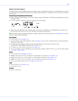
installing or using your Adaptec product, check this document first-you will find answers to most of your questions. If you need further assistance, use the support options listed below. To expedite your service, have your computer in front of you. Technical Support Identification (TSID) Number - Adaptec 51645 | User Guide - Page 4
is available to the purchaser by delivering the product during the warranty period to an authorized Adaptec service facility or to Adaptec and providing proof of purchase price and date. The purchaser shall bear all shipping, packing and insurance costs and all other costs, excluding labor and - Adaptec 51645 | User Guide - Page 5
, Inc. Use only with the listed ITE: Adaptec RAID 5085/Adaptec RAID 5405/Adaptec RAID 5445/ Adaptec RAID 5805/ Adaptec RAID 5405Z/Adaptec RAID 5805Z/Adaptec RAID 5445Z/ Adaptec RAID 51245/Adaptec RAID 51645/Adaptec RAID 52445/ Adaptec RAID 2045/Adaptec RAID 2405 Tested to Comply With FCC Standards - Adaptec 51645 | User Guide - Page 6
Adding a Battery Backup Module 17 Upgrading the Controller Firmware 17 About the Adaptec RAID 5085 18 About the Adaptec RAID 5405 19 About the Adaptec RAID 5445 20 About the Adaptec RAID 5805 21 About the Adaptec RAID 51245 22 About the Adaptec RAID 51645 23 About the Adaptec RAID 52445 24 - Adaptec 51645 | User Guide - Page 7
Drives and other SSDs 40 Connecting External Devices 42 Next Steps ...42 Creating a Bootable Array Setting the Boot Controller 44 Creating an Array 44 Creating an Array with the ACU 44 Creating an Array with Adaptec Storage Manager 46 Making Your Array Bootable 47 Installing the Driver and an - Adaptec 51645 | User Guide - Page 8
60 About the Adaptec RAID Controller Configuration Utility 60 About the Adaptec RAID Configuration Utility 61 About the Adaptec Flash Utility 61 Which Utility Should I Use 61 Solving Problems Troubleshooting Checklist 63 Monitoring Disk Drives Status 63 Silencing the Alarm 63 Recovering from - Adaptec 51645 | User Guide - Page 9
75 Non-redundant Arrays (RAID 0 75 RAID 1 Arrays 76 RAID 1 Enhanced Arrays 76 RAID 10 Arrays 77 RAID 5 Arrays 78 RAID 5EE Arrays 79 RAID 50 Arrays 80 RAID 6 Arrays 81 RAID 60 Arrays 81 Selecting the Best RAID Level 82 Using the Adaptec RAID Configuration Utility Introduction to the - Adaptec 51645 | User Guide - Page 10
104 Obtaining the Firmware 104 Creating the Firmware Update Disks 105 Running the Menu-based AFU 105 Running the AFU from the Command Line 106 AFU Commands 106 Updating the Flash Using the AFU Command Line 109 Controller LED and I2C Connector Quick Reference Adaptec RAID 5085 LED Connector - Adaptec 51645 | User Guide - Page 11
(SAS) and Redundant Array of Independent Disk (RAID) technology. These RAID controller models are described in this Guide: ● Adaptec RAID 5085 ● Adaptec RAID 5405/5405Z ● Adaptec RAID 5445/5445Z ● Adaptec RAID 5805/5805Z ● Adaptec RAID 51245 ● Adaptec RAID 51645 ● Adaptec RAID 52445 ● Adaptec RAID - Adaptec 51645 | User Guide - Page 12
the Adaptec Storage Manager software; accessible from the main window of Adaptec Storage Manager. ● Adaptec RAID Controller Command Line Utility User's Guide-Describes how to use the included Adaptec RAID Controller Configuration (ARCCONF) command line utility (see page 60) to perform basic array - Adaptec 51645 | User Guide - Page 13
Kit Contents and System Requirements 2 In this chapter... Kit Contents...14 System Requirements ...14 This chapter lists the contents of your Adaptec RAID controller kit and the system requirements that must be met for you to successfully install and use your controller. - Adaptec 51645 | User Guide - Page 14
.com.) ● (Selected models only) Low-profile bracket ● Adaptec Serial Attached SCSI RAID Controllers Quick Start Guide System Requirements ● PC-compatible computer with Intel Pentium, or equivalent, processor ● Motherboard with these features: ● Support for multifunction devices where one of the - Adaptec 51645 | User Guide - Page 15
Adding a Battery Backup Module 17 Upgrading the Controller Firmware 17 About the Adaptec RAID 5085 18 About the Adaptec RAID 5405 19 About the Adaptec RAID 5445 20 About the Adaptec RAID 5805 21 About the Adaptec RAID 51245 22 About the Adaptec RAID 51645 23 About the Adaptec RAID 52445 24 - Adaptec 51645 | User Guide - Page 16
3: About Your RAID Controller ● 16 Standard RAID Controller Features ● Support for SAS disk drives, SATA/SATA II disk drives, SATA Solid State Drives (SSD), and Adaptec MaxIQ™ Solid State Drives ● Flash ROM for updates to controller firmware, BIOS, and the Adaptec RAID Configuration utility ● Disk - Adaptec 51645 | User Guide - Page 17
Module This table shows the battery model supported by your Adaptec RAID controller. RAID Controller Adaptec RAID 5085/Adaptec RAID 5405/Adaptec RAID 5445/Adaptec RAID 5805/ Adaptec 51245/Adaptec 51645/Adaptec 52445 Battery Model Adaptec Battery Module 800 Adaptec Battery Module 800T To purchase - Adaptec 51645 | User Guide - Page 18
the Adaptec RAID 5085 The Adaptec RAID 5085 is a SAS RAID controller with these features: Ext. Alarm Aggregate Activity Mode 0 Flash connector Activity LEDs Diagnostic LEDs Audible Alarm Drive Activity LED connectors for CN1/CN0 CN0 CN1 2 external SAS connectors Mounting bracket Battery - Adaptec 51645 | User Guide - Page 19
5405 The Adaptec RAID 5405 is a SAS RAID controller with these features: Drive Activity LED connectors for CN0/CN1 Drive Activity LEDs for CN0/CN1 Mode 0 Flash connector Aggregate Activity Diagnostic LEDs Internal mini-SAS connector CN0 Status CN0 PCIe x8 connector Mounting bracket Ext. Alarm - Adaptec 51645 | User Guide - Page 20
3: About Your RAID Controller ● 20 About the Adaptec RAID 5445 The Adaptec RAID 5445 is a SAS RAID controller with these features: Drive Activity CN1/CN0 Status CN1/CN0 Mode 0 Flash connector Ext. Alarm External miniSAS connector CN1 Diagnostic LEDs (back of card) Internal mini-SAS connector CN0 - Adaptec 51645 | User Guide - Page 21
Ext. Alarm connector Form Factor Bus compatibility PCIe bus width PCIe bus speed Phys (Unified Serial Ports) Standard cache Connectors, internal Maximum number of disk drives Enclosure Support Onboard speaker Battery Backup Module Low-profile MD2 PCIe x8 2.5 Gb/s 8 512 MB DDR2 2 mini-SAS x4 - Adaptec 51645 | User Guide - Page 22
the Adaptec RAID 51245 The Adaptec RAID 51245 is a SAS RAID controller with these features: I2C, CN2 Mode 0 Flash Activity CN2 I2C, CN1 I2C, CN0 Activity CN0, CN1 CN6 1 external mini-SAS connector ABM-800 connector CN0 CN1 CN2 3 internal mini-SAS connectors Reserved Ext. Alarm Aggregate - Adaptec 51645 | User Guide - Page 23
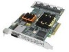
RAID 51645 The Adaptec RAID 51645 is a SAS RAID controller with these features: I2C, CN2 I2C, CN3 Mode 0 Flash Activity CN2, CN3 Activity CN0, CN1 CN6 1 external mini-SAS connector I2C, CN1 I2C, CN0 CN0 CN1 4 internal mini-SAS connectors CN2 CN3 ABM-800 connector Reserved Ext. Alarm - Adaptec 51645 | User Guide - Page 24
Reserved Ext. Alarm Aggregate Activity Activity CN4, CN5 Form Factor Bus compatibility PCIe bus width PCIe bus speed Phys (Unified Serial Ports) Standard cache Connectors, Internal Connectors, Exteneral Maximum number of disk drives Enclosure Support Onboard speaker Battery Backup Module Full - Adaptec 51645 | User Guide - Page 25
Chapter 3: About Your RAID Controller ● 25 About the Adaptec RAID 5405Z The Adaptec RAID 5405Z is a SAS RAID controller with these features: Drive Activity LED connectors for CN0 Drive Activity LEDs for CN0 I2C connector for CN0 Ext. Alarm connector Aggregate Activity Mode 0 Flash connector - Adaptec 51645 | User Guide - Page 26
Chapter 3: About Your RAID Controller ● 26 About the Adaptec RAID 5445Z The Adaptec RAID 5445Z is a SAS RAID controller with these features: Drive Activity LED connectors for CN0/CN1 Drive Activity LEDs for CN0/CN1 I2C connectors for CN0/CN1 Ext. Alarm connector Aggregate Activity Mode 0 Flash - Adaptec 51645 | User Guide - Page 27
Chapter 3: About Your RAID Controller ● 27 About the Adaptec RAID 5805Z The Adaptec RAID 5805Z is a SAS RAID controller with these features: Drive Activity LED connectors for CN0/CN1 Drive Activity LEDs for CN0/CN1 I2C connectors for CN0/CN1 Ext. Alarm connector Aggregate Activity Mode 0 Flash - Adaptec 51645 | User Guide - Page 28
Chapter 3: About Your RAID Controller ● 28 About the Adaptec RAID 2045 The Adaptec RAID 2045 is a SAS RAID controller with these features: Aggregate Activity Mode 0 Flash connector CN1 1 external miniSAS connector Mounting bracket PCIe x8 connector Form Factor Bus compatibility PCIe bus width - Adaptec 51645 | User Guide - Page 29
Your RAID Controller ● 29 About the Adaptec RAID 2405 The Adaptec RAID 2405 is a SAS RAID controller with these features: Activity connector for CN0 Aggregate Activity Mode 0 Flash connector Internal mini-SAS connector CN0 Mounting bracket I2C, CN0 PCIe x8 connector Form Factor Bus compatibility - Adaptec 51645 | User Guide - Page 30
you need to set up your disk drives and arrays the way you want them. It also describes the options you have for installing your Adaptec controller and disk drives, and creating arrays for data storage. - Adaptec 51645 | User Guide - Page 31
you begin, familiarize yourself with your Adaptec controller's physical features and the RAID levels that it supports (see Standard RAID Controller Features on page 16). ● RAID 0 (Non-redundant Array)-Stripes data across multiple disk drives. Improved performance but no redundancy (see page 75 - Adaptec 51645 | User Guide - Page 32
Drives and Cables Disk Drives Your SAS controller supports SAS disk drives, SATA disk drives, SATA Solid State Drives (SSD), and Adaptec MaxIQ Solid State Drives. When selecting disk drives for your RAID array, ensure that all the disk drives have the same performance level. You can use different - Adaptec 51645 | User Guide - Page 33
using only Adaptec SAS cables. For more information or to purchase cables, visit the Adaptec Web site at www.adaptec.com. Installation Options When you install your Adaptec controller, you can choose to create a bootable array and then install your operating system and the controller driver on that - Adaptec 51645 | User Guide - Page 34
, you can connect external disk drives as well (or instead). 2 Set the boot controller (see page 44). 3 Create a bootable array (see page 44). 4 Install your operating system and the controller driver (see page 48.) 5 Install Adaptec Storage Manager and begin to manage your data storage (see page 59 - Adaptec 51645 | User Guide - Page 35
5 In this chapter... Before You Begin ...36 Installing the Controller...36 Connecting Disk Drives to Your Controllers 38 Connecting External Devices 42 Next Steps ...42 This chapter explains how to install your Adaptec RAID controller, and how to install and connect internal and external disk - Adaptec 51645 | User Guide - Page 36
an Adaptec RAID controller with zero maintenance cache protection, see page 37. Installing a RAID Controller 1 Turn off your computer and disconnect the power cord. Open the cabinet, following the manufacturer's instructions. 2 Select an available PCIe expansion slot that's compatible with your RAID - Adaptec 51645 | User Guide - Page 37
Adaptec RAID controller with Zero Maintenance Cache Protection. The battery module can overheat and may even explode! 1 Turn off your computer and disconnect the power cord. Open the cabinet, following the manufacturer's instructions. 2 Select an available PCIe expansion slot that's compatible with - Adaptec 51645 | User Guide - Page 38
page 42. Connecting Disk Drives to Your Controllers You can connect SAS disk drives, SATA disk drives, SATA Solid State Drives (SSD), and Adaptec MaxIQ Solid State Drives to your SAS RAID controller. (See www.adaptec.com/ compatibility for a list of compatible disk drives.) There are no jumpers or - Adaptec 51645 | User Guide - Page 39
drives have been installed and attached to the controller, close your computer cabinet, reattach the power cord, then continue with Connecting External Devices on page 42. Connecting to a System Backplane In a backplane connection, disk drives and SAS cards are attached to and communicate with each - Adaptec 51645 | User Guide - Page 40
MaxIQ SSD kit). Note: For MaxIQ caching applications, Adaptec RAID controllers support Adaptec MaxIQ- branded/Intel X25-E Solid State Drives only. For RAID arrays, you can use any Solid State Drive on the compatibility list, including Adaptec MaxIQ SSDs. (See www.adaptec.com/compatibility for a list - Adaptec 51645 | User Guide - Page 41
MaxIQ SSDs to a controller. For RAID arrays, Adaptec RAID controllers support a maximum of 256 drives, including SSDs (for details, see page 15). Note: The following steps use an Adaptec MaxIQ SSD as an example, but the procedure is suitable for any compatible SSD. 1 Install your Adaptec MaxIQ SSDs - Adaptec 51645 | User Guide - Page 42
in the following example. Internal x4 mini-SAS connector To other SSDs Single-port connector MaxIQ SSD connected to controller with internal mini-SAS to SATA Fanout cable (SFF-8087 to 4x-SATA) 3 When all SSDs have been installed and connected, close your computer cabinet, reattach the power cord - Adaptec 51645 | User Guide - Page 43
...44 Creating an Array ...44 Making Your Array Bootable 47 This chapter explains how to set your Adaptec controller to be the boot controller, and how to create a bootable array. Note: If you are completing a standard installation onto an existing operating system, you don't have to complete - Adaptec 51645 | User Guide - Page 44
section). ● Adaptec Storage Manager-Graphical software application (running from a bootable RAID installation CD) that you can navigate with your mouse (see page 60). ● ARCCONF-Command line utility. For instructions, refer to the Adaptec RAID Controller Command Line Utility User's Guide. You can - Adaptec 51645 | User Guide - Page 45
screen opens, follow the instructions in the following table. Property Line Array Caching Write Caching Create RAID via [Done] Entry or Selection Select RAID 5, then press Enter. You can start using the array immediately. However, performance is reduced until the build process is complete. 12 - Adaptec 51645 | User Guide - Page 46
Installation CD to complete this task. To create a RAID 5 array: 1 Insert the Adaptec Storage Manager Installation CD into your CD drive, then restart your computer. 2 When prompted, select the language you want, then press Enter. 3 Review the license information, then press Enter. The main menu - Adaptec 51645 | User Guide - Page 47
as a full software application, refer to the Adaptec Storage Manager User's Guide or online Help. 12 Continue with the following section. Making Your Array Bootable Use the ACU to make the array bootable (see Creating Bootable Arrays on page 85). Then continue with Installing the Driver and an - Adaptec 51645 | User Guide - Page 48
with Red Hat Linux 51 Installing with SUSE Linux...51 Installing with OpenServer ...51 Installing with UnixWare ...52 Installing with Solaris...52 Installing with VMware ...53 Installing with FreeBSD ...53 This chapter explains how to install your Adaptec RAID controller driver and an operating - Adaptec 51645 | User Guide - Page 49
.) 2 Turn on your computer, then insert the RAID Installation CD included in your RAID controller kit. 3 Follow the on-screen instructions to get to the Adaptec Start Menu. 4 Click Create Driver Disk(s) for Installing/Updating your OS, then select your operating system. Note: Linux only-If prompted - Adaptec 51645 | User Guide - Page 50
page 59. Installing with Windows Server 2008 or Windows Vista To install the Adaptec RAID controller driver while installing Windows: 1 Insert your Windows CD, then restart the computer. 2 Follow the on-screen instructions to begin the Windows installation. 3 When prompted to specify a location for - Adaptec 51645 | User Guide - Page 51
, following the instructions included with your operating system. 8 Continue with Managing Your Storage Space on page 59. Installing with SUSE Linux To install the Adaptec RAID controller driver while installing SUSE Linux: 1 Insert the first SUSE Installation CD. 2 Restart your computer. 3 When the - Adaptec 51645 | User Guide - Page 52
UnixWare Note: You will need your UnixWare Installation CD to complete this task. To install the driver when installing UnixWare: 1 Insert the UnixWare Installation CD. 2 Restart your computer. 3 Follow the on-screen instructions to begin the UnixWare installation. 4 When prompted to load more HBA - Adaptec 51645 | User Guide - Page 53
. If the driver fails to load, run lsdev and check for the floppy disk drive. Then, try again with the appropriate device. 7 Type boot. 8 Complete the FreeBSD installation, following the instructions included with your operating system. 9 Reboot your computer, then remove the driver disk. 10 Repeat - Adaptec 51645 | User Guide - Page 54
on Red Hat or SUSE Linux 56 Installing on OpenServer ...57 Installing on UnixWare ...57 Installing on Solaris...57 Installing on VMware...58 Installing on FreeBSD ...58 This chapter explains how to install your Adaptec RAID controller driver. Note: To install the driver while you're installing an - Adaptec 51645 | User Guide - Page 55
.) 2 Turn on your computer, then insert the RAID Installation CD included in your RAID controller kit. 3 Follow the on-screen instructions to get to the Adaptec Start Menu. 4 Click Create Driver Disk(s) for Installing/Updating your OS, then select your operating system. Note: Linux only-If prompted - Adaptec 51645 | User Guide - Page 56
. 4 When the installation is complete, remove the driver disk and restart your computer. 5 Continue with Managing Your Storage Space on page 59. Installing on Red Hat or SUSE Linux To install the module on Red Hat or SUSE Linux: 1 Insert and mount the RAID Installation CD: Red Hat: mount /dev/cdrom - Adaptec 51645 | User Guide - Page 57
is no pre-existing Adaptec driver on your computer, continue with Step 3. If an Adaptec driver is already installed on your computer, perform a pkgrm SUNWaac to remove it. ! Caution: If your operating system currently boots from the Adaptec controller, do not reset your computer after you remove the - Adaptec 51645 | User Guide - Page 58
for your VMware distribution. 4 Follow the on-screen instructions to save the boot image and run the vmware-mkinitrd command manually. 5 Reboot your computer and remove the driver disk. Note: Currently, the Adaptec Storage Manager GUI is not supported on VMware. To create and manage arrays, you - Adaptec 51645 | User Guide - Page 59
60 About the Adaptec RAID Controller Configuration Utility 60 About the Adaptec RAID Configuration Utility 61 About the Adaptec Flash Utility 61 Which Utility Should I Use 61 Once you have installed your Adaptec RAID controller, disk drives (or other devices), and device driver, you can begin - Adaptec 51645 | User Guide - Page 60
instructions, refer to the Adaptec Storage Manager User's Guide, also included on the Adaptec Storage Manager Installation CD. About the Adaptec RAID Controller Configuration Utility The Adaptec RAID Controller Configuration (ARCCONF) is a command line utility that you can use to perform - Adaptec 51645 | User Guide - Page 61
correctly to avoid rendering your RAID controller inoperable.Adaptec recommends that only advanced users familiar with working in DOS use the AFU. You can also use Adaptec Storage Manager to update the controller firmware/BIOS. See the Adaptec Storage Manager User's Guide for more information. Which - Adaptec 51645 | User Guide - Page 62
Solving Problems 10 In this chapter... Troubleshooting Checklist ...63 Silencing the Alarm ...63 Recovering from a Disk Drive Failure 64 Resetting the Controller...65 This chapter provides basic troubleshooting information and solutions for solving controller problems. - Adaptec 51645 | User Guide - Page 63
on page 71. For more information about using Adaptec Storage Manager to monitor your disk drives, refer to the Adaptec Storage Manager User's Guide or the online Help. Silencing the Alarm If your Adaptec RAID controller includes an alarm, the alarm will sound when an error occurs. To silence - Adaptec 51645 | User Guide - Page 64
drives, and controllers are properly installed and connected. Make sure that the new disk drive is equal or greater in size than the failed disk drive. Then, if necessary, use Adaptec Storage Manager to rebuild the array. For instructions, refer to the Adaptec Storage Manager User's Guide or online - Adaptec 51645 | User Guide - Page 65
upgrade is unsuccessful. To reset your Adaptec RAID controller: 1 Download the firmware version currently installed on your controller from www.adaptec.com 2 Extract the downloaded files to a folder on your local hard drive (for example, C:\Download\Drivers). 3 Create a bootable MS-DOS floppy disk - Adaptec 51645 | User Guide - Page 66
Problems ● 66 5 Power off your computer, disconnect the power cord, then open the cabinet following the manufacturer's instructions. 6 Disconnect all cables from the controller, then attach a shorting jumper to the Mode 0 flash connector. (To locate the Mode 0 flash connector on your Adaptec RAID - Adaptec 51645 | User Guide - Page 67
from Parallel SCSI 73 This section provides a basic overview of the main features of SAS, introduces some common SAS terms, and explains how SAS differs from parallel SCSI. Note: For technical articles and tutorials about SAS, refer to the SCSI Trade Association (STATM) Web site at www.scsita.org - Adaptec 51645 | User Guide - Page 68
● 68 Terminology Used in This Chapter For convenience, SAS HBAs and SAS RAID controllers are referred to generically in this chapter as SAS cards. HBAs, RAID controllers, disk drives, and external disk drive enclosures are referred to as end devices and expanders are referred to as expander devices - Adaptec 51645 | User Guide - Page 69
from a phy in one port to a phy in the other port. As shown in the figure above, a wide port can support multiple independent links simultaneously. Phys are internal, within SAS connectors (see page 70). SAS cables physically connect one or more phys on one SAS device to one or more phys on another - Adaptec 51645 | User Guide - Page 70
of RAID controllers and storage devices. A port is one or more phys. A narrow port contains one phy. A wide port typically contains four phys. Each port has its own unique SAS address (see page 71), and all the phys in a port share that same SAS address. SAS card port options vary. A SAS card with - Adaptec 51645 | User Guide - Page 71
Your RAID Controller on page 15 for your RAID controller Activity LED connections and locations. Once you have connected to a backplane, the Adaptec Storage Manager enables you to manage your disk drives. For more information, refer to the Adaptec Storage Manager User's Guide on the Adaptec Storage - Adaptec 51645 | User Guide - Page 72
Appendix A: Introduction to SAS ● 72 Some backplanes support daisy-chain expansion to other backplanes. For example, you can daisy-chain (connect one to the next) up to nine Adaptec S50 enclosures to a single SAS card in a host system. SAS Expander Connections A SAS expander device literally - Adaptec 51645 | User Guide - Page 73
SCSI IDs Requires bus termination Standard SCSI connectors Serial Attached SCSI Serial interface Maximum speed 300 MB/sec per phy when in halfduplex mode Supports SATA and SAS disk drives simultaneously More than 100 disk drives per SAS card, using an expander (see page 72) or 50 SATAII disk drives - Adaptec 51645 | User Guide - Page 74
level to protect your data. Each RAID level offers a unique combination of performance and redundancy. RAID levels also vary by the number of disk drives they support. This appendix describes the RAID levels supported by your Adaptec RAID controller, and provides a basic overview of each to help - Adaptec 51645 | User Guide - Page 75
0 arrays do not maintain redundant data, so they offer no data protection. Compared to an equal-sized group of independent disks, a RAID 0 array provides improved I/O performance. Drive segment size is limited to the size of the smallest disk drive in the array. For instance, an array with two 250 - Adaptec 51645 | User Guide - Page 76
one disk drive is a mirror of the other (the same data is stored on each disk drive). Compared to independent disk drives, RAID 1 arrays provide improved performance, with twice the read rate and an equal write rate of single disks. However, capacity is only 50 percent of independent disk drives - Adaptec 51645 | User Guide - Page 77
10 array is built from two or more equal-sized RAID 1 arrays. Data in a RAID 10 array is both striped and mirrored. Mirroring provides data protection, and striping improves performance. Drive segment size is limited to the size of the smallest disk drive in the array. For instance, an array with - Adaptec 51645 | User Guide - Page 78
and parity data to provide redundancy. Parity data provides data protection, and striping improves performance. Parity data is an error-correcting redundancy that's used to re-create data if a disk drive fails. In RAID 5 arrays, parity data (represented by Ps in the next figure) is striped evenly - Adaptec 51645 | User Guide - Page 79
and can't be shared with other logical disk drives. A distributed spare improves the speed at which the array is rebuilt following a disk drive failure. A RAID 5EE array protects your data and increases read and write speeds. However, capacity is reduced by two disk drives' worth of space, which is - Adaptec 51645 | User Guide - Page 80
, and stripes stored data and parity data across all disk drives in both RAID 5 arrays. (For more information, see RAID 5 Arrays on page 78.) The parity data provides data protection, and striping improves performance. RAID 50 arrays also provide high data transfer speeds. Drive segment size is - Adaptec 51645 | User Guide - Page 81
extra protection for your data because they can recover from two simultaneous disk drive failures. However, the extra parity calculation slows performance (compared to RAID 5 arrays). RAID 6 arrays must be built from at least four disk drives. Maximum stripe size depends on the number of disk drives - Adaptec 51645 | User Guide - Page 82
logical drives on your storage space, based on the number of available disk drives and your requirements for performance and reliability. RAID Level RAID 0 RAID 1 RAID 1E RAID 10 RAID 5 RAID 5EE RAID 50 RAID 6 RAID 60 Redundancy No Yes Yes Yes Yes Yes Yes Yes Yes Disk Drive Usage 100% 50% 50% 50 - Adaptec 51645 | User Guide - Page 83
the Event Log ...92 The Adaptec RAID Configuration (ARC) utility is a BIOS-based utility that you can use to create and manage controllers, disk drives and other devices, and arrays. Note: Adaptec recommends that only advanced users familiar with working in a computer BIOS use the ARC utility tools - Adaptec 51645 | User Guide - Page 84
displays: "Adaptec RAID Configuration Utility will load after, system initialization. Please wait... Or press Key to attempt loading the utility forcibly [Generally, not recommended]" Note: The first time you power on your computer after you install a new controller, the BIOS may display - Adaptec 51645 | User Guide - Page 85
to avoid permanently losing it. Creating Bootable Arrays Note: You may need to change the system BIOS to modify the boot order. For more information, refer to your computer documentation. The controller always uses the lowest numbered array as its bootable array. To make an array bootable: 1 Select - Adaptec 51645 | User Guide - Page 86
Adaptec RAID MaxIQ cache uses the Adaptec MaxIQ Solid State Drives in your system as a read cache pool to improve performance in read-intensive applications. the message "Initializing drives...FAILED x of n" is displayed. Press Enter to see a list of drives that failed to initialize. Press Esc to - Adaptec 51645 | User Guide - Page 87
utility (see page 84). If you have more than one controller, select your controller, then press Enter. Select Array Configuration Utility, then press Enter. Follow the on-screen instructions to create and manage JBODs. Creating a New JBOD A JBOD disk appears as a physical disk drive to the operating - Adaptec 51645 | User Guide - Page 88
For more information about compatible drives, refer to the Adaptec Web site at www.adaptec.com/compatibility. To add an SSD to the MaxIQ pool or to remove an SSD from the MaxIQ pool: 1 Start the ARC utility (see page 84). If you have more than one controller, select your controller, then press Enter - Adaptec 51645 | User Guide - Page 89
rebuilds an array when a failed disk drive is replaced. When disabled, the array must be rebuilt manually. When enabled, the controller constantly verifies a redundant array. Note that there may be a significant performance reduction. Default is disabled. When enabled in systems that support - Adaptec 51645 | User Guide - Page 90
available on all RAID controller models.) Note-CD's are not supported by current software. Removable Media When enabled, removable media devices, such as CD drives, are Devices Boot Support supported. (This setting is not available on all RAID controller models.) Alarm Control When enabled, the - Adaptec 51645 | User Guide - Page 91
Appendix C: Using the Adaptec RAID Configuration Utility ● 91 PHY Settings Note: These details are read-only and non-editable. Option Description PHY Rate The data transfer rate between the controller and devices. The default setting is Auto, which allows the SAS card to adjust the data - Adaptec 51645 | User Guide - Page 92
the Adaptec RAID Configuration Utility ● 92 Identifying Disk Drives You can identify disk drives by viewing the list of disk drives on your system. Only physical drives that display during POST are shown. To identify a disk drive: 1 Start the ARC utility (see page 84). 2 Select the controller you - Adaptec 51645 | User Guide - Page 93
Configuration Utility (ACU) for DOS, a text-based utility that you can use to create, configure, and manage arrays. (A BIOS-based ACU is also available. See page 84.) Note: Adaptec recommends that only advanced users familiar with working in DOS use the ACU for DOS utility. For more information, see - Adaptec 51645 | User Guide - Page 94
a floppy disk which you can create using the RAID Installation CD that came in your Adaptec RAID controller kit. To create the ACU floppy disk: 1 Insert your RAID Installation CD into the CD drive, then browse to this file: packages/firmware/controllermodel/acu.exe Where controllermodel is the model - Adaptec 51645 | User Guide - Page 95
. The computer boots to the DOS command line. 2 Type ACU on the command line, specify a script file, and specify either the /P or /R switches listed in the See page 95. /R Record Mode-The ACU writes a RAID controller's existing array configuration to a specified script file, which lets you - Adaptec 51645 | User Guide - Page 96
also create a script file manually (see the following section). In Record Mode, the ACU writes a RAID controller's existing array configuration to the file is placed in the same location as the ACU executable. The ACU supports only a subset of available array types. If it encounters an array it can - Adaptec 51645 | User Guide - Page 97
and Type. Array definition keywords and descriptions are listed in this table. Keyword Array Drives End HotspareDrives No default. See page 98. No Indicates whether to initialize all the drives connected to the controller. Default is No. See page 98. Yes Indicates the method (Build/Verify, Clear, - Adaptec 51645 | User Guide - Page 98
Once a pool spare is used by a failed disk drive, however, it is no longer list to all arrays within the multilevel array. InitializeAll Keyword If you want the ACU to initialize all drives connected to the controller once. InitializeAll is always performed prior to array creation regardless - Adaptec 51645 | User Guide - Page 99
overall array performance. Maximum performance is achieved by starting and completing a Build/Verify. ● Skip Init-If multiple disk drives fail in the same specifies the stripe size (in KB) written to each member of a striped array (RAID 0, 10, 5, 5, 5EE, 50, 6 or 60). The possible values for StripeSize are - Adaptec 51645 | User Guide - Page 100
RAID1, RAID5, RAID10, or RAID50. Depending on the RAID levels supported by your RAID controller, additional possible values are: RAID1E, RAID5EE, RAID6, listed in this table. Code Description 0 ACU ran without changes-ACU exited with no errors (success) and no report is required. 1 No controller - Adaptec 51645 | User Guide - Page 101
Incorrect controller number. 16 Controller not responding. 17 Build/Verify/Clear failed. 18 Cannot use drives on shared channel. 21 Failed the computer. Sample Scripts This command invokes the ACU and creates arrays on controller 1 based on the array keywords defined in the script file A:\RAID.ACU. - Adaptec 51645 | User Guide - Page 102
write cache WriteCache=No # Assign 1 spare drive HotspareDrives=0:3:0 End This sample script file creates a maximum-size three-disk-drive RAID 5: # Create a maximum size RAID 5 labeled 'MyData' Array=MyData Type=RAID5 Size=Maximum # Use the maximum stripe size StripeSize=1024 # Clear the array (don - Adaptec 51645 | User Guide - Page 103
Using the AFU Command Line 109 This chapter describes how to use the Adaptec Flash Utility (AFU), a text-based DOS utility that you can use to update, save, or verify the RAID controller's firmware BIOS and NVRAM. ! Caution: Although the AFU contains safeguards to prevent you from accidentally - Adaptec 51645 | User Guide - Page 104
obtain RAID controller firmware, go to: ● The RAID Installation CD-Includes the AFU executable (AFU.exe) and a separate flash image. The flash image may comprise multiple User Flash Image (UFI) files. ● The Adaptec Web site-Download a new firmware file to get the most recent version of firmware/BIOS - Adaptec 51645 | User Guide - Page 105
the system setup utility and change the setting. 2 Insert the firmware update disk (created using the steps above) containing AFU.exe 3 At the DOS command prompt, type AFU with no arguments. The AFU's main menu is displayed. 4 Select Select Controllers, then select the Adaptec RAID controller(s) to - Adaptec 51645 | User Guide - Page 106
success or an error message code. To update a RAID controller's flash using the command line utility ARCCONF, see page 109. AFU Commands This section lists the available AFU commands. List Displays the AFU-supported RAID controllers installed on your computer. Also displays the ID numbers assigned - Adaptec 51645 | User Guide - Page 107
system response after an update. A:\> AFU UPDATE /C 0 Adaptec Flash Utility V4.0-0 B5749 (c)Adaptec Inc. 1999-2005. All Rights Reserved. Updating Controller 0 (Adaptec RAID 31205) Reading flash image file (Build 5749) AFU is about to update firmware on controllers Adaptec RAID 51645 ***PLEASE DO NOT - Adaptec 51645 | User Guide - Page 108
ID>] This example displays version information about all supported RAID controllers. A:\> AFU VERSION /C 0 Adaptec Flash Utility V4.0-0 B5749 (c)Adaptec Inc. 1999-2005. All Rights Reserved. Version Information for Controller #0 (Adaptec RAID 51645) ROM: Build 5748 [VALID] Fri Sep 27 13:28:40 - Adaptec 51645 | User Guide - Page 109
instructions suitable for your requirements: ● To update a single RAID controller: AFU UPDATE /C Where is the number of the RAID controller whose firmware you are updating. For example, to upgrade Controller 0, type AFU UPDATE /C 0 ● To update multiple RAID controllers - Adaptec 51645 | User Guide - Page 110
Adaptec RAID 51645 LED and I2C Connector Specification 120 Adaptec RAID 52445 LED and I2C Connector Specification 122 Adaptec RAID 2045 LED Connector Specification 125 Adaptec RAID 2405 LED and I2C Connector Specification 125 This chapter provides a reference guide for Adaptec® RAID controllers - Adaptec 51645 | User Guide - Page 111
Controller LED and I2C Connector Quick Reference ● 111 Adaptec RAID 5085 LED Connector Specification 2249100-R ASR-5085/512MB RoHS SGL ● Adaptec RAID LED Cathode LED Anode ● Adaptec RAID 5085 External Alarm Connector: Molex 22-28-4023 or equivalent ● Alarm Mating Cable Connector: Molex 50 - Adaptec 51645 | User Guide - Page 112
Appendix F: Controller LED and I2C Connector Quick Reference ● 112 J12: J12 Pin Number 2 1 Signal ~2kHz Square Wave +3.3V Description Open collector transistor ● Adaptec RAID 5085 Status LED Board Connector: Molex 10-89-7162 or equivalent ● Status LED Mating Cable Connector: Molex 22-55-2161 or - Adaptec 51645 | User Guide - Page 113
Appendix F: Controller LED and I2C Connector Quick Reference ● 113 Adaptec RAID 5405/5405Z LED and I2C Connector Specification 2258100-R 2258100JA-R 2258200-R 2266800-R ASR-5405 RoHS KIT ASR-5405/JA RoHS KIT ASR-5405 RoHS Single ASR-5405Z RoHS Single ● Adaptec RAID 5405/5405Z Activity LED Header - Adaptec 51645 | User Guide - Page 114
Cathode LED Anode LED Cathode 22-55-2161 Pin Number 2 1 4 3 6 5 8 7 Adaptec RAID 5445/5445Z LED and I2C Connector Specification 2228800-R 2244900-R 2267000-R ASR-5445 RoHS Kit ASR-5445/512MB RoHS SGL ASR-5445Z RoHS Single ● Adaptec RAID 5445/5445Z Activity LED Header Connector: Molex 10-89-7162 - Adaptec 51645 | User Guide - Page 115
Appendix F: Controller LED and I2C Connector Quick Reference ● 115 J2 Pin Number 5 6 7 8 9 2 ACTIVITY 1 +3.3V Description LED Cathode LED Anode ● Adaptec RAID 5445/5445Z External Alarm Connector: Molex 22-28-4023 or equivalent ● Alarm Mating Cable Connector: Molex 50-57-9002 or equivalent J12: - Adaptec 51645 | User Guide - Page 116
Appendix F: Controller LED and I2C Connector Quick Reference ● 116 J14 (Adaptec RAID 5445 Adaptec RAID 5805/5805Z LED and I2C Connector Specification 2244100-R 2244100JA-R 2244300-R 2266900-R ASR-5805 RoHS KIT ASR-5805/JA RoHS KIT ASR-5805/512MB RoHS Single ASR-5805Z RoHS Single ● Adaptec RAID - Adaptec 51645 | User Guide - Page 117
Appendix F: Controller LED and I2C Connector Quick Reference ● 117 J2 Pin Number 8 9 10 2 ACTIVITY 1 +3.3V Description LED Cathode LED Anode ● Adaptec RAID 5805/5805Z External Alarm Connector: Molex 22-28-4023 or equivalent ● Alarm Mating Cable Connector: Molex 50-57-9002 or equivalent J12: - Adaptec 51645 | User Guide - Page 118
LED Cathode 22-55-2161 Pin Number 2 1 4 3 6 5 8 7 10 9 12 11 14 13 16 15 Adaptec RAID 51245 LED and I2C Connector Specification 2258400-R 2258300-R ASR-51245 RoHS Kit ASR-51245 RoHS Single ● Adaptec RAID 51245 Activity LED Header Connector for CN0/CN1: Molex 10-89-7162 or equivalent ● Activity - Adaptec 51645 | User Guide - Page 119
Appendix F: Controller LED and I2C Connector Quick Reference ● 119 J3 Pin Number 3 4 5 6 7 8 9 Cathode 22-55-2161 Pin Number 4 3 6 5 8 7 10 9 12 11 14 13 16 15 ● Adaptec RAID 51245 Activity LED Board Connector for CN2: Molex 10-89-7162 or equivalent ● Activity LED Mating Cable Connector: Molex - Adaptec 51645 | User Guide - Page 120
or equivalent J28, J29, J30: J2x Pin Number 3 2 1 Signal I2C Clock Ground I2C Data Adaptec RAID 51645 LED and I2C Connector Specification 2258500-R 2258600-R ASR-51645 RoHS Kit ASR-51645 RoHS Single ● Adaptec RAID 51645 Activity LED Header Connector for CN0/CN1: Molex 10-89-7162 or equivalent - Adaptec 51645 | User Guide - Page 121
Appendix F: Controller LED and I2C Connector Quick Reference ● 121 J3 Pin Number 8 9 10 11 12 LED Anode LED Cathode 22-55-2161 Pin Number 7 10 9 12 11 14 13 16 15 ● Adaptec RAID 51645 Activity LED Board Connector for CN2/CN3: Molex 10-89-7162 or equivalent ● Activity LED Mating Cable Connector - Adaptec 51645 | User Guide - Page 122
Appendix F: Controller LED and I2C Connector Quick Reference ● 122 J10: J10 Pin Number 2 1 Signal ACTIVITY +3.3V Description LED Cathode LED Anode ● Adaptec RAID 51645 External Alarm Connector: Molex 22-28-4023 or equivalent ● Alarm Mating Cable Connector: Molex 50-57-9002 or equivalent J12: - Adaptec 51645 | User Guide - Page 123
Appendix F: Controller LED and I2C Connector Quick Reference ● 123 J3 Pin Number 9 10 Cathode 22-55-2161 Pin Number 2 1 4 3 6 5 8 7 10 9 12 11 14 13 16 15 ● Adaptec RAID 52445 Activity LED Header Connector for CN4/CN5: Molex 10-89-7162 or equivalent ● Activity LED Header Mating Cable Connector: - Adaptec 51645 | User Guide - Page 124
Appendix F: Controller LED and I2C Connector Quick Reference ● 124 J2 Pin Number 3 4 5 6 7 8 1 Signal ACTIVITY +3.3V Description LED Cathode LED Anode ● Adaptec RAID 52445 External Alarm Connector: Molex 22-28-4023 or equivalent ● Alarm Mating Cable Connector: Molex 50-57-9002 or equivalent J12: - Adaptec 51645 | User Guide - Page 125
Controller LED and I2C Connector Quick Reference ● 125 Adaptec RAID 2045 LED Connector Specification 2260300-R ASR-2045 RoHS SGL ● Adaptec RAID LED Anode Adaptec RAID 2405 LED and I2C Connector Specification 2260100-R 2260200-R ASR-2405 RoHS KIT ASR-2405 RoHS SGL ● Adaptec RAID 2405 Activity - Adaptec 51645 | User Guide - Page 126
Appendix F: Controller LED and I2C Connector Quick Reference ● 126 ● Adaptec RAID 2405 I2C Board Connector : Molex 22-43-6030 or equivalent ● I2C Mating Cable Connector: Molex 22-43-3030 or equivalent J4: J4 Pin Number 3 2 1 Signal I2C Clock Ground I2C Data - Adaptec 51645 | User Guide - Page 127
your work area and the computer clean and clear of debris controller by its bracket or edges only. Avoid touching the printed circuit board or the connectors. ● Put the controller down only on an antistatic surface such as the bag supplied in your kit. ● If you are returning the controller to Adaptec - Adaptec 51645 | User Guide - Page 128
Technical Specifications H In this appendix... Environmental Specifications 129 DC Power Requirements...129 Current Requirements...129 - Adaptec 51645 | User Guide - Page 129
Specifications Note: Adaptec RAID controllers require adequate airflow to operate reliably. The recommended airflow is 200 LFM. Forced airflow is recommended. Ambient temperature with forced airflow Ambient temperature without forced airflow Ambient temperature with Battery Backup Unit - Adaptec 51645 | User Guide - Page 130
support 3 Adaptec Flash Utility. See AFU Adaptec RAID Configuration utility 61, 83 to 92 Adaptec RAID Controller Configuration utility. See ARCCONF Adaptec Storage Manager 60 creating arrays 46 installing 60 adapters. See controllers advanced data protection 16 AFU 61, 103 to 109 Alarm Control - Adaptec 51645 | User Guide - Page 131
During POST setting 90 RAID levels 31 Removable Media Devices Boot Support setting 90 resetting 65 Runtime BIOS setting 89 SAS Address setting 91 SAS cables 32 setting boot controller 44 specifications 128 standard features troubleshooting 63 updating firmware 104 upgrading firmware 17 copyback 16 - Adaptec 51645 | User Guide - Page 132
devices 42 F failed disk drives 64 multiple arrays 64 multiple disk drives 65 RAID 0 arrays 65 without hot spare 64 firmware 104 creating floppy disks 105 firmware upgrades 17 flashing controllers 65 floppy disks for firmware update 105 formatting disk drives 91 FreeBSD driver installation 58 OS - Adaptec 51645 | User Guide - Page 133
Performance Mode 90 Serial Attached SCSI. See SAS SerialSelect 88 applying changes 89 exiting 89 modifying controller settings 89 opening 89 software 60 Solaris driver installation 57 Solid State Drive (SSD) 16, 32, 38, 86, 88 installing 40 to 42 specifications 128 storage management Adaptec RAID - Adaptec 51645 | User Guide - Page 134
installation 57 OS installation 52 updating firmware 104 upgrading firmware 17 utilities Adaptec RAID Controller utility 61 AFU 61 ARCCONF 60 V verifying disk drives 91 VMWare driver installation 58 OS installation 53 W Windows driver installation 56 OS installation 49 Z zero maintenance cache - Adaptec 51645 | User Guide - Page 135
Adaptec, Inc. 691 South Milpitas Boulevard Milpitas, CA 95035 USA ©2009 Adaptec, Inc. All rights reserved. Adaptec and the Adaptec logo are trademarks of Adaptec, Inc. which may be registered in some jurisdictions. Part Number: CDP-00243-05-A Rev. A JB 10/09
-
 1
1 -
 2
2 -
 3
3 -
 4
4 -
 5
5 -
 6
6 -
 7
7 -
8
-
9
-
10
-
11
-
12
-
13
-
14
-
15
-
16
-
17
-
18
-
19
-
20
-
21
-
22
-
23
-
24
-
25
-
26
-
27
-
28
-
29
-
30
-
31
-
32
-
33
-
34
-
35
-
36
-
37
-
38
-
39
-
40
-
41
-
42
-
43
-
44
-
45
-
46
-
47
-
48
-
49
-
50
-
51
-
52
-
53
-
54
-
55
-
56
-
57
-
58
-
59
-
60
-
61
-
62
-
63
-
64
-
65
-
66
-
67
-
68
-
69
-
70
-
71
-
72
-
73
-
74
-
75
-
76
-
77
-
78
-
79
-
80
-
81
-
82
-
83
-
84
-
85
-
86
-
87
-
88
-
89
-
90
-
91
-
92
-
93
-
94
-
95
-
96
-
97
-
98
-
99
-
100
-
101
-
102
-
103
-
104
-
105
-
106
-
107
-
108
-
109
-
110
-
111
-
112
-
113
-
114
-
115
-
116
-
117
-
118
-
119
-
120
-
121
-
122
-
123
-
124
-
125
-
126
-
127
-
128
-
129
-
130
-
131
-
132
-
133
-
134
-
135
 |
 |
Installation and User’s Guide
Serial Attached SCSI RAID Controllers