Adaptec 1966600 User Guide
Adaptec 1966600 - DuraStor 7220SS Hard Drive Array Manual
 |
UPC - 760884139202
View all Adaptec 1966600 manuals
Add to My Manuals
Save this manual to your list of manuals |
Adaptec 1966600 manual content summary:
- Adaptec 1966600 | User Guide - Page 1
INSTALLATION AND USER'S GUIDE DURASTOR 6220SS/7220SS - Adaptec 1966600 | User Guide - Page 2
DuraStor 6220SS/7220SS Installation and User's Guide R - Adaptec 1966600 | User Guide - Page 3
this document, or from the use of the information contained herein. Adaptec reserves the right to make changes in the product design without reservation and without notification to its users. Disclaimer IF THIS PRODUCT DIRECTS YOU TO COPY MATERIALS, YOU MUST HAVE PERMISSION FROM THE COPYRIGHT OWNER - Adaptec 1966600 | User Guide - Page 4
and if not installed and used in accordance with the instruction manual, may cause harmful interference to radio communications. Operation Technology Equipment has been tested and found to comply with the following European directives: EMC Directive 89/336/EEC, as amended by 92/31/EEC and 93/68/EEC - Adaptec 1966600 | User Guide - Page 5
Contents 1 Introduction About This Guide 1-1 Installation Overview 1-2 Storage Management Software Tools 1-2 Adaptec Storage Manager Pro 1-2 Adaptec Disk Array Administrator 1-3 The Operator Control Panel 1-3 2 About the DuraStor Storage Subsystem About the DuraStor RAID Appliances 2-1 Front Bezel - Adaptec 1966600 | User Guide - Page 6
DuraStor 6220SS/7220SS Installation and User's Guide Setting Up the DuraStor 312R Storage Enclosure 3-6 Removing the Front the Host System HBA to Multiple-LUN Support 3-22 Completing the Connections for the DuraStor 7220SS 3-23 Connecting the Fibre Channel-to-SCSI RAID Appliance to the DuraStor 312R - Adaptec 1966600 | User Guide - Page 7
5-10 Replacing a Power Supply Unit 5-11 Replacing the Disk I/O Card 5-13 Replacing the SAF-TE Controller Card 5-14 Replacing the DuraStor 312R Chassis 5-15 6 Troubleshooting Problems with the DuraStor RAID Appliance 6-1 Problems with the DuraStor 312R Storage Enclosure 6-2 A Port Information B The - Adaptec 1966600 | User Guide - Page 8
of the DuraStor Fibre Channel-to-SCSI RAID Appliance and the DuraStor 312R) This Guide does not describe the DuraStor 6200S or 7200S RAID controller. For information, refer to the DuraStor 6200S/7200S RAID Controller Installation Guide for installation instructions and product specifications. This - Adaptec 1966600 | User Guide - Page 9
Guide tools are provided in separate user's guides provided on the DuraStor CD. See Storage Management Software Tools on page 1-2. This Guide instructions move directly to the Adaptec Storage Manager Pro We recommend using the Storage Manager Pro software application. It is included on the DuraStor CD - Adaptec 1966600 | User Guide - Page 10
rear panel of the DuraStor RAID appliance. See Accessing Disk Array Administrator on page 3-56 for detailed instructions. You can find the Adaptec Disk Array Administrator User's Guide on the DuraStor CD. The Operator Control Panel If you don't have a computer monitor available and cannot use one of - Adaptec 1966600 | User Guide - Page 11
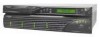
and using it. About the DuraStor RAID Appliances This section provides illustrated descriptions of the main features of the DuraStor RAID appliances, both SCSI and Fibre Channel-toSCSI. Figure 2-1 provides an overview of both the RAID appliances from the front. Both RAID appliances look similar from - Adaptec 1966600 | User Guide - Page 12
and User's Guide Controller 1 Canister Chassis Post Controller 2 Canister adaptec Power Supply Unit 2 Power Supply Unit 1 MENU ENTER ESCAPE SCTOANTTURSOLLER 1 ACTIVITY SCTOANTUTRSOLLER 2 ACTIVITY POWER FAULT Front Bezel Figure 2-1. Front View of the DuraStor SCSI RAID Appliance Figure - Adaptec 1966600 | User Guide - Page 13
units. See Figure 2-4. It also houses the OCP buttons, the LCD panel, and the Power, Fault, and Controller LEDs. adaptec MMEENNUU ENTER EESSCCAAPEPE Operator Control Panel Buttons LCD Panel Power LED SCTOANTTURSOLLER 1 ACTIVITY SCTOANTUTRSOLLER 2 ACTIVITY POWER FAULT Controller LEDs Fault - Adaptec 1966600 | User Guide - Page 14
DuraStor 6220SS/7220SS Installation and User's Guide Operator Control Panel (OCP) The OCP is located on the the hardware you need to install a second controller. The DuraStor Fibre Channel-to-SCSI RAID appliance contains one DuraStor 7200S RAID controller preinstalled; the second controller canister - Adaptec 1966600 | User Guide - Page 15
About the DuraStor Storage Subsystem Power System The DuraStor RAID appliance power system consists of two hot-swappable, power supply units (PSUs) and two AC power cord connectors. This system provides the appliance with an N+1 redundant power system. Each PSU has auto-switching circuitry for 110/ - Adaptec 1966600 | User Guide - Page 16
DuraStor 6220SS/7220SS Installation and User's Guide Figure 2-7 shows the AC power cord connectors on the back of the chassis. The security bales hold the power cords in place and prevent accidental - Adaptec 1966600 | User Guide - Page 17
I/O Connectivity Panel The I/O connectivity panel of the SCSI RAID appliance connects the host computer (server) to the storage enclosure disk drives. See Figure 2-9 for detailed connection information. Connects to Host System or to Storage Enclosure I/O Card HOST 1 IN (CH 3) HOST 2 IN (CH 0) DISK - Adaptec 1966600 | User Guide - Page 18
DuraStor 6220SS/7220SS Installation and User's Guide Additionally, two 68-pin very-high-density SCSI connectors connect to the disk channels of the DuraStor 312R storage enclosure. From left to LEDs. Table 2-1 summarizes the specific technical specifications of the DuraStor SCSI RAID appliance. 2-8 - Adaptec 1966600 | User Guide - Page 19
About the DuraStor Storage Subsystem Table 2-1. DuraStor SCSI RAID Appliance Technical Specifications Operating Environment Relative Humidity Class A CISPR 22 EN55022-A UL1950 CSA #950 TUV/EN60950 89/336/EEC EMC Directive 1.0 G, 2-50 ms 20.0 G, 2-20 ms 5-500 Hz, 0.25 G (pk to pk) 5-500 Hz, 1.0 G - Adaptec 1966600 | User Guide - Page 20
DuraStor 6220SS/7220SS Installation and User's Guide Fibre Channel-to-SCSI RAID Appliance I/O Connectivity Panel The I/O connectivity panel of the Fibre Channel-to-SCSI RAID appliance connects the host computer (server) to the storage enclosure disk drives. See Figure 2-10 for detailed connection - Adaptec 1966600 | User Guide - Page 21
being used or not. Setting this switch to EXT will not disable the front bezel LEDs. Optical SFP Transceiver The Fibre Channel-to-SCSI RAID appliance uses a hot-swappable Small Form Factor Pluggable (SFP) transceiver. The SFP optical transceiver provides operations up to 2.5 Gb/sec. The transceiver - Adaptec 1966600 | User Guide - Page 22
DuraStor 6220SS/7220SS Installation and User's Guide The SFP transceiver is Class 1 Laser safety compliant and conforms to Class 1 eye safety standards. Warning: Do not look into the laser light beam for - Adaptec 1966600 | User Guide - Page 23
specific technical specifications of the DuraStor Fibre Channel-to-SCSI RAID appliance. Table 2-2. DuraStor Fibre Channel RAID Appliance 22 EN55022-A VCCI, BSMI, C-TICK UL1950 CSA #950 TUV/EN60950 89/336/EEC EMC Directive 1.0 G, 2-50 ms 20.0 G, 2-20 ms 5-500 Hz, 0.25 G (pk to pk) 5-500 Hz, 1.0 G ( - Adaptec 1966600 | User Guide - Page 24
and User's Guide About the DuraStor can be found in Table 2-5 on page 2-24. Bezel Lip adaptec Drive LEDs Disk Drive in Carrier Chassis Drive LEDs Reset Alarm Front View of the DuraStor 312R Storage Enclosure SAF-TE Controller Card Power Supply Units OGUOTOPUDT 0 1 FAULT OGUOTOPUDT 0 1 FAULT - Adaptec 1966600 | User Guide - Page 25
. It also houses the audible alarm, the alarm reset button, the Status LEDs, and the Drive Status and Drive Activity LEDs. See Figure 2-15. adaptec Drive Status and Drive Activity LEDs Status LEDs Reset Alarm Alarm Reset Button Figure 2-15. DuraStor 312R Front Bezel Screw When the bezel is - Adaptec 1966600 | User Guide - Page 26
Installation and User's Guide Disk Drives The DuraStor 312R storage enclosure uses high-performance, 80pin, 3.5-inch, 1-inch high, hot-swappable SCA disk drives. See Figure 2-16. For information on DuraStor 312R-compatible disk drives, go to the Adaptec Web site at www.adaptec.com/go/ durastor - Adaptec 1966600 | User Guide - Page 27
About the DuraStor Storage Subsystem Power Supply Units The DuraStor 312R storage enclosure has two independent hotswappable power supply units (PSU). See Figure 2-18. Each PSU has auto-sensing/load-sharing circuitry that balances the load between the power supplies. If a PSU fails, the load is - Adaptec 1966600 | User Guide - Page 28
drive bay area and the back two fans cool the interface cards and power supply chamber. Warning!triDhfeaFmanamonfvaiveMgedeomfdwouirinlllemuotieocssrce.ur A B FANS Figure 2-19. DuraStor 312R Cooling Fan Module The SCSI-Accessed Fault Tolerant Enclosure (SAF-TE) processor monitors the temperature and - Adaptec 1966600 | User Guide - Page 29
(Input) and Channel 2 (Output). Note: The DuraStor 312R does not support High Voltage Differential (HVD) SCSI. Also located on the disk I/O card are three sets of jumpers. Two of the jumpers, JP1 and JP3, route termination power to the SCSI bus. The default setting is jumpered (a jumper on both pins - Adaptec 1966600 | User Guide - Page 30
See Powering Off on page 3-54. The SAF-TE controller card monitors the disk drives, PSUs, cooling fans, and enclosure temperature, and continually reports conditions to the host system. It also sets the drive ID (drive configuration), the SCSI bus mode, and the disk drive start/spinup options. 2-20 - Adaptec 1966600 | User Guide - Page 31
a fixed SCSI target ID, allowing standard alert detection and status reporting with the SCSI bus as the DuraStor 312R SAF-TE Switches UP Position = 1 DOWN Position = 0 The SAF-TE controller card sets the disk drive configuration. It has eight switches that control many settings. Note: By default - Adaptec 1966600 | User Guide - Page 32
(0) configures the enclosure for singlebus mode. In this configuration, all 12 disk drives are on a single SCSI bus and are accessed through the Channel 1 Input connector on the disk I/O card. See Disk I/O Card on page 2-19. The UP position (1) configures the enclosure for dual-bus mode. In this - Adaptec 1966600 | User Guide - Page 33
7 and 8 control the drive spin-up functions. The switches are directly attached to all of the disk drive slot start signals. Switch 7 Drive motor does not spin up. Up (1) Down (0) Drive motor spins up only on SCSI Start command. Down (0) Up (1) Drive motor spins up after a delay of 12 seconds - Adaptec 1966600 | User Guide - Page 34
7220SS Installation and User's Guide Table 2-5 summarizes the Altitude Number of Drives Supported Total Capacity Host Interface 200 to 10,000 ft 12 per enclosure 876 GB (73 GB Drives) Ultra160 SCSI SCA-80 Ultra160 SCSI RS-232 (power supply, temperature, and fan monitoring) FCC, Part 15, Class - Adaptec 1966600 | User Guide - Page 35
Your Storage Management Tool 3-54 This chapter explains how to set up the complete storage subsystem (DuraStor 6220SS/7220SS); however, the installation instructions can be followed if you are only setting up one of the two components. If you are installing either the DuraStor RAID appliance or - Adaptec 1966600 | User Guide - Page 36
DuraStor 6220SS/7220SS Installation and User's Guide Storage Subsystem Installation Overview 1. Setting Up the DuraStor RAID System. See page 3-29. c Setting the Host System HBA to Multiple-LUN Support. See page 3-22. (DuraStor SCSI RAID appliance only.) d Turning On the Power. See page 3-54. 4. - Adaptec 1966600 | User Guide - Page 37
appliance. Removing the Front Bezel 1 Unlock the front bezel by turning the screws one-quarter turn to the left. See Figure 3-1. adaptec MENU ENTER ESCAPE SCTOANTUTRSOLLER 1 A CTIVITY SCTOANTUTRSOLLER 2 A CTIVITY PO WER FAULT Figure 3-1 Unlocking the Front Bezel 2 Using both hands, pull the - Adaptec 1966600 | User Guide - Page 38
DuraStor 6220SS/7220SS Installation and User's Guide Mounting the RAID Appliance on the Rack The RAID appliance can be installed into any standard 19-inch rack. Installation tips: It will be helpful - Adaptec 1966600 | User Guide - Page 39
Installing the DuraStor Storage Subsystem 4 Slide one of the rack's mounting rails into the slot on the left side of the RAID appliance's back panel. See Figure 3-8. Push the rail in until it fits the depth of the rack. The rail should mate with mounting slots on the rack's rear vertical member and - Adaptec 1966600 | User Guide - Page 40
DuraStor 6220SS/7220SS Installation and User's Guide Replacing the Front Bezel 1 Ensure that the front bezel mounts to the two posts and that the bezel lip fits under the chassis top. 2 Lock - Adaptec 1966600 | User Guide - Page 41
Installing the DuraStor Storage Subsystem Removing the Front Bezel 1 Unlock the front bezel by turning the screws one-quarter turn to the left. See Figure 3-5. adaptec Reset Alarm Figure 3-5 Unlocking the Front Bezel 2 Using both hands, pull the front bezel from the enclosure. See Figure 3-6. - Adaptec 1966600 | User Guide - Page 42
DuraStor 6220SS/7220SS Installation and User's Guide Mounting the Storage Enclosure on the Rack The appliance chassis during installation. See Replacing a Power Supply Unit on page 5-5 for detailed instructions. 2 Select a location within your rack. If you are installing the DuraStor 6220SS/7200SS - Adaptec 1966600 | User Guide - Page 43
Installing the DuraStor Storage Subsystem Front Rack Vertical Member Chassis Ear Nut Mounting Screw Figure 3-7 Attaching the Chassis Ears 5 Slide one of the rack's mounting rails into the slot on the left side of the storage enclosure's back panel. See Figure 3-8. Push the rail in until it fits - Adaptec 1966600 | User Guide - Page 44
DuraStor 6220SS/7220SS Installation and User's Guide 6 Secure the left side rail to the vertical member using to a Drive Carrier 1 Place the disk drive component-side down on a flat surface, with the SCSI connector facing away from you. 2 Slide the drive carrier over the disk drive so that the handle - Adaptec 1966600 | User Guide - Page 45
have installed the DuraStor SCSI RAID appliance or the DuraStor 312R but not both, go directly to the sections SCSI RAID appliance to the DuraStor 312R(s). See page 3-12. s Connect the DuraStor SCSI RAID appliance to the host system. See page 3-17. s Set the host system HBA to multiple-LUN support - Adaptec 1966600 | User Guide - Page 46
7220SS Installation and User's Guide Connecting the SCSI RAID Appliance to the DuraStor 312R This section explains how to connect the DuraStor SCSI RAID appliance to the DuraStor 312R storage enclosure(s) and how to set the drive configuration. You can connect the DuraStor SCSI RAID appliance to up - Adaptec 1966600 | User Guide - Page 47
HOST 1 IN (CH 3) HOST 2 IN (CH 0) HOST 1 OUT HOST 2 OUT Disk CH 2 Disk CH 1 Serial B Ext Serial A Int DuraStor 312R SCSI Data Cable SCSI Data Cable 1 2 3 4 5 6 78 Disk I/O Channel 2 Channel 1 (Output) (Input) Figure 3-11 Dual-Bus 2-12-Drive Cabling Diagram Connecting to Two Storage - Adaptec 1966600 | User Guide - Page 48
DuraStor 6220SS/7220SS Installation and User's Guide 2 Connect the DuraStor SCSI RAID appliance to the DuraStor 312R using SCSI data cables, as shown in Figure 3-13. DuraStor SCSI RAID Appliance Disk CH 2 Disk CH1 HOST 1 IN (CH 3) HOST 2 IN (CH 0) HOST 1 OUT HOST 2 OUT Disk CH 2 Disk CH 1 - Adaptec 1966600 | User Guide - Page 49
available when you are using a single controller in your DuraStor SCSI RAID appliance. One of the host channels-Host In (CH to a single Host In port. 1 Establish the drive configuration by setting the SAF-TE card switches to reflect the settings shown in Figure 3-14. SAF-TE ID = 15 RAID - Adaptec 1966600 | User Guide - Page 50
DuraStor 6220SS/7220SS Installation and User's Guide DuraStor SCSI RAID Appliance Disk CH 2 Disk CH1 HOST 1 IN (CH 3) HOST 2 IN (CH 0) HOST 1 OUT HOST 2 OUT Disk CH 2 Disk CH 1 Serial B Ext Serial A Int DuraStor 312R SCSI Data Cable 1 2 3 4 5 6 78 Disk I/O Channel 2 Channel 1 ( - Adaptec 1966600 | User Guide - Page 51
Host System This section explains how to connect the DuraStor SCSI RAID appliance to the host system in one of (on active 2 controller only) Refer to Adaptec Storage Manager Pro User's Guide or Adaptec Disk Array Administrator User's Guide for more detailed information about each operating mode. - Adaptec 1966600 | User Guide - Page 52
ID 7. Refer to your host system's user's guide for details on setting HBA SCSI IDs. 3 Power on the DuraStor Storage Subsystem. See Powering On on page 3-54. 4 Set the controller operating mode. For detailed instructions, refer to the user's guide for the storage management tool you are using. 3-18 - Adaptec 1966600 | User Guide - Page 53
ID 7. Refer to your host system's user's guide for details on setting HBA SCSI IDs. 3 Power on the DuraStor Storage Subsystem. See Powering On on page 3-54. 4 Set the controller operating mode. For detailed instructions, refer to the user's guide for the storage management tool you are using. 3-19 - Adaptec 1966600 | User Guide - Page 54
controller configuration where Host 2 In (CH 0), Host 1 In (CH 3), Disk CH 1, or Disk CH 2 are not cabled. 2 Set the host system HBA to SCSI ID 7. Refer to your host system's user's guide for details on setting HBA SCSI IDs. 3 Power on the DuraStor External Storage Subsystem. See page 3-54. 3-20 - Adaptec 1966600 | User Guide - Page 55
and failback, and support for optional upstream SCSI ID 7. Refer to your host system's user's guide for details on setting HBA SCSI IDs. 3 Power on the DuraStor External Storage Subsystem. See page 3-54. 4 Set the controller operating mode. For detailed instructions, refer to the user's guide - Adaptec 1966600 | User Guide - Page 56
DuraStor 6220SS/7220SS Installation and User's Guide Changing Your Drive Configuration You may need follow the setup instructions for that mode as provided in Connecting the SCSI RAID Appliance to the Host System on page 3-17. Setting the Host System HBA to Multiple-LUN Support Before your host - Adaptec 1966600 | User Guide - Page 57
methods for connecting and configuring the DuraStor 7220SS storage subsystem. If you have installed the DuraStor Fibre Channel-to-SCSI RAID appliance or the DuraStor 312R but not both, go directly to the sections that apply to you. To complete the installation and setup of the DuraStor 7220SS, you - Adaptec 1966600 | User Guide - Page 58
DuraStor 6220SS/7220SS Installation and User's Guide Connecting to One Storage Enclosure (2-12 Figure 3-20 12-Drive Switch Settings 2 Connect the DuraStor Fibre Channel-to-SCSI RAID appliance to the DuraStor 312R using SCSI data cables as shown in Figure 3-21. DuraStor FC RAID Appliance Disk CH - Adaptec 1966600 | User Guide - Page 59
Figure 3-20 on page 3-24. Use the same switch settings for both storage enclosures. 2 Connect the DuraStor Fibre Channel-to-SCSI RAID appliance to the DuraStor 312R using SCSI data cables as shown in Figure 3-22. DuraStor FC RAID Appliance Disk CH 3 Disk CH 2 Disk CH 0 Disk CH 1 P-2 P-1 Serial - Adaptec 1966600 | User Guide - Page 60
DuraStor 6220SS/7220SS Installation and User's Guide Connecting to Three Storage Enclosures (25-36-Drive Configuration) 1 Establish the drive configuration by setting the SAF-TE switches to reflect the settings shown in - Adaptec 1966600 | User Guide - Page 61
Installing the DuraStor Storage Subsystem 2 Connect the DuraStor Fibre Channel-to-SCSI RAID appliance to the DuraStor 312R using SCSI data cables as shown in Figure 3-24. DuraStor FC RAID Appliance Disk CH 3 Disk CH 2 Disk CH 0 Disk CH 1 P-2 P-1 Serial B P-3 P-4 Ext Serial A Int - Adaptec 1966600 | User Guide - Page 62
/7220SS Installation and User's Guide Connecting to Four Storage Enclosures (37-48-Drive Configuration) 1 Establish the drive configuration by setting the SAF-TE switches to reflect the settings shown in Figure 3-23 on page 3-26. 2 Connect the DuraStor Fibre Channel-to-SCSI RAID appliance to the - Adaptec 1966600 | User Guide - Page 63
Manager Pro User's Guide or Adaptec Disk Array Administrator User's Guide for more detailed information about each operating mode. To connect the DuraStor Fibre Channel-to-SCSI RAID appliance to the host system: 1 Insert the SFP Transceivers into the FC (Fibre Channel) ports that are intended - Adaptec 1966600 | User Guide - Page 64
DuraStor 6220SS/7220SS Installation and User's Guide a On each end of the optical FC data cable and on the SFP . See Powering On on page 3-54. 4 Set the controller operating mode. For detailed instructions, refer to the user's guide for the storage management software tool you are using. 3-30 - Adaptec 1966600 | User Guide - Page 65
Installing the DuraStor Storage Subsystem Important Information About SAN Environments In configurations where there are multiple paths from the host server to the DuraStor, each partition (defined as a FC LUN) is presented to the host as many times as there are paths. For example, if there are two - Adaptec 1966600 | User Guide - Page 66
DuraStor 6220SS/7220SS Installation and User's Guide Figure 3-29 Four Data Paths - Example A Figure 3-30 Four Data Paths - Example B Since each partition defined on the DuraStor is presented to all hosts connected - Adaptec 1966600 | User Guide - Page 67
to a Storage Area Network (SAN), see SAN Solution Strategies on page 3-46. The DuraStor 7220SS supports many different topologies. To optimize and simplify all of the supported topologies, three user selectable operating modes are available. The operating modes are chosen based on performance - Adaptec 1966600 | User Guide - Page 68
6220SS/7220SS Installation and User's Guide These modes address everything from direct attach single controller configuration to full system-level faulttolerant disk storage solution. This dual controller configuration supports multiple hosts and has true failover and failback operations. All host - Adaptec 1966600 | User Guide - Page 69
four ports are passive. This configuration is ideal when the host driver software will not support LUN zoning, as would be the case in active-active About Stand-Alone Mode In Stand-Alone mode, the Fibre Channel-to-SCSI RAID controller operates autonomously. In dual-host port operation, there are up - Adaptec 1966600 | User Guide - Page 70
6220SS/7220SS Installation and User's Guide Another advantage is that with an appropriate host driver, the host has a redundant . A host device driver may provide this functionality. Hosts can detect redundant paths to an array by matching array serial numbers from SCSI inquiry data. About Active - Adaptec 1966600 | User Guide - Page 71
Installing the DuraStor Storage Subsystem ! Caution: When in active-active mode, the two controllers communicate with each other using SCSI initiator IDs 6 and 7 on the disk channels. The values of 6 and 7 are mandatory defaults to guarantee good communication between the two controllers, and you - Adaptec 1966600 | User Guide - Page 72
DuraStor 6220SS/7220SS Installation and User's Guide Stand-Alone Dual-Port (Hubs Disabled) The following diagram illustrates the logical connection of the stand-alone dual-port topology with the hubs disabled. DuraStor - Adaptec 1966600 | User Guide - Page 73
Installing the DuraStor Storage Subsystem 4 Press the Esc to return to the previous menu. 5 From the Option Configuration menu, select Enclosure Services, then select Config Internal Hubs. 6 Choose the selection to Disable the Internal Hub then press the Enter. 7 Press Esc to return to the previous - Adaptec 1966600 | User Guide - Page 74
DuraStor 6220SS/7220SS Installation and User's Guide FC HBA 1 FC HBA 2 (soft ID) (soft ID) Host Computer DuraStor FC RAID Appliance Fibre Channel Data Cable P3 Fibre Channel Data Cable P4 Disk - Adaptec 1966600 | User Guide - Page 75
press Enter to set this selection. 4 Press Esc to return to the previous menu. 5 (Hub Selection, if required) From the Option Configuration menu, select Enclosure Services, then select Config Internal Hubs. 3-41 - Adaptec 1966600 | User Guide - Page 76
DuraStor 6220SS/7220SS Installation and User's Guide 6 Choose the selection to Disable the Internal Hub, then press Enter to set this selection. 7 Press Esc to return to the previous menu. Active-Active - Adaptec 1966600 | User Guide - Page 77
Installing the DuraStor Storage Subsystem FC HBA 1 (Soft ID) Second Host Computer FC HBA 2 (Soft ID) Fibre data cables FC HBA 2 (Soft ID) FC HBA 1 (Soft ID) First Host Computer DuraStor FC RAID Appliance P1 P3 P2 P4 Disk CH 3 Disk CH 2 Disk CH 0 Disk CH 1 P-2 P-1 Serial B P-3 P-4 Ext - Adaptec 1966600 | User Guide - Page 78
DuraStor 6220SS/7220SS Installation and User's Guide DuraStor FC RAID Appliance To FC Switch P2 select Configuration, then select Option Configuration. 3 From the Option Configuration menu, select Enclosure Services, then select Config Internal Hubs. 4 Select Disable the Internal Hub. 5 Press Esc - Adaptec 1966600 | User Guide - Page 79
Installing the DuraStor Storage Subsystem Note: Ports P1 and P3 are on one loop, and P2 and P4 are on another loop. DuraStor FC RAID Appliance PHYSICAL FC PORTS DRIVE CHANNELS CH0 CH0 FC2 Active CH1 FC1 Passive CH2 CH1 Controller 2 CH3 Host System #1 HBA #2 P2 HUB ACTIVE FC PORTS - Adaptec 1966600 | User Guide - Page 80
DuraStor 6220SS/7220SS Installation and User's Guide SAN Solution Strategies This section describes connecting the DuraStor online. In the event of a controller failure, two FC ports remain available to service all host I/O. Table 3-3 illustrates how LUNs are presented by each controller in this - Adaptec 1966600 | User Guide - Page 81
Installing the DuraStor Storage Subsystem Hubs Enabled In the following figures, the DuraStor 7220SS storage subsystem's two controllers are configured in an active-active dual-port mode with the internal hubs enabled. In Figure 3-42, two hosts are connected via two independent loops using the - Adaptec 1966600 | User Guide - Page 82
DuraStor 6220SS/7220SS Installation and User's Guide Figure 3-43 illustrates the conditions when Controller 2 fails. Note that both hosts can still see Controller 1's LUNs (LUN 1) and Controller 2's LUN (LUN 2); however, each host - Adaptec 1966600 | User Guide - Page 83
-active dual-port mode with the internal hubs disabled. In Figure 3-44, two hosts are connected via two independent switches. Using external switches supports higher bandwidth, since the host ports are not required to share bandwidth on a loop. DuraStor FC RAID Appliance Host 1 FC HBA Sees LUN - Adaptec 1966600 | User Guide - Page 84
DuraStor 6220SS/7220SS Installation and User's Guide In Figure 3-45, two hosts are connected via two independent switches. Note that both hosts can still see Controller 1's LUNs (LUN 1) and Controller 2's LUNs (LUN 2); - Adaptec 1966600 | User Guide - Page 85
-active dual-port mode, because of increased connectivity. However, the host driver software would need to handle the fact that each LUN would appear twice The advantages of using a switch is that the two hosts each have a direct path to a controller port and don't have to compete for access on the - Adaptec 1966600 | User Guide - Page 86
DuraStor 6220SS/7220SS Installation and User's Guide Hubs Disabled (Single External Hub) Figure 3-47 shows the hosts in a single loop using an external hub connected to the DuraStor 7220SS storage subsystem's two - Adaptec 1966600 | User Guide - Page 87
independent hubs or the internal hub, two single-ported hosts are not supported. The issue with this configuration is that if a controller fails, each hubs and controllers have redundant hardware, but the hosts do not. The problem with this configuration can be overcome by using a single switch at - Adaptec 1966600 | User Guide - Page 88
DuraStor 6220SS/7220SS Installation and User's Guide Turning On the Power Note: Ensure that none of the data cables or power cables are obstructing Control Panel (OCP) of the DuraStor RAID appliance. Refer to the DuraStor RAID Appliance Operating Control Panel User's Guide for instructions. 3-54 - Adaptec 1966600 | User Guide - Page 89
reinstalling it. You must also delete the old StorageManagerPro directory. To uninstall Storage Manager Pro, refer to the Adaptec Storage Manager Pro User's Guide. When you install Storage Manager Pro for Windows, you automatically install Java Runtime Environment (JRE) 1.1.8, which is required - Adaptec 1966600 | User Guide - Page 90
and User's Guide 4 Click OK. The Storage Manager Pro Introduction window appears. 5 Follow the on-screen instructions to complete the can now perform all of the functions described in the Adaptec Storage Manager Pro User's Guide. Warning: We strongly recommend that you regularly and consistently - Adaptec 1966600 | User Guide - Page 91
Table 3-4. Table 3-4 RS-232 Serial Port Settings Setting Terminal Emulation Font Translations Columns Value VT-100 or ANSI (for color support) Terminal None 80 Set the communications parameters for the terminal program as shown in Table 3-5. Table 3-5 Communications Parameter Settings Setting - Adaptec 1966600 | User Guide - Page 92
software. Be sure that your terminal emulator software is set to use the correct COM port on your computer. Refer to the Adaptec Disk Array Administrator User's Guide for more details on how the DuraStor 6200S/7200S RAID controller can auto-detect the baud rate. 4 Press CTRL-R. The initial Disk - Adaptec 1966600 | User Guide - Page 93
the system. This chapter describes the functions of the LEDs and alarms on the DuraStor RAID appliance and the DuraStor 312R. For complete instructions on using your storage management tool to monitor your system, refer to the user's guide for the storage management software tool you are using. 4-1 - Adaptec 1966600 | User Guide - Page 94
DuraStor 6220SS/7220SS Installation and User's Guide Monitoring the DuraStor RAID Appliance Front Bezel LEDs There are six LEDs located on the front bezel of the DuraStor RAID appliance. See Figure 4-1. s Power - Adaptec 1966600 | User Guide - Page 95
alarm, let the controller continue to operate. If it is a shutdown alarm, turn off the power to the controller, remove it, and send it for service. Same as for VCC voltage. 4-3 - Adaptec 1966600 | User Guide - Page 96
DuraStor 6220SS/7220SS Installation and User's Guide The Operator Control Panel For information on 4-4 explain how to interpret these LEDs. Status Indicator LEDs Power On LED Channel Status LED adaptec Power Supply Status LED Fan Status LED Drive Status LEDs (Left Column of LEDs) Drive Activity - Adaptec 1966600 | User Guide - Page 97
Monitoring the DuraStor Storage Subsystem Status LEDs There are four Status LEDs. Table 4-3 explains how to interpret the different colors and conditions they display. Table 4-3. Status LEDs LED Power On Channel Status Power Supply Status Fan Status Color and Condition Green (solid) Green (solid - Adaptec 1966600 | User Guide - Page 98
DuraStor 6220SS/7220SS Installation and User's Guide The Drive Status LED (on the left) indicates the good drive LEDs. Hot spare, rebuild mode (all Drive Status LEDs). Empty drive slot. Drive manually disabled (applies to LVD-LVD only). Array is fault-tolerant. Array is in rebuild mode. Array - Adaptec 1966600 | User Guide - Page 99
changes to an abnormal state. To silence the alarm, press the Alarm Reset button on the front bezel. The LED indicating the location of the problem stays illuminated until normal status returns. 4-7 - Adaptec 1966600 | User Guide - Page 100
5-1 Maintaining the DuraStor 312R Storage Enclosure 5-7 This chapter provides complete instructions for maintaining the DuraStor RAID appliance and the DuraStor 312R. Visit the Adaptec Web site at www.adaptec.com for information on replacement parts. Maintaining the DuraStor RAID Appliance This - Adaptec 1966600 | User Guide - Page 101
RAID appliance. See Figure 5-1. Latches Open Figure 5-1. Removing the Controller 5 Install the replacement controller in the controller canister. Refer to your controller's installation guide and/or the DuraStor 6200S/7200S External RAID Controller Installation Guide for detailed instructions. 5-2 - Adaptec 1966600 | User Guide - Page 102
when there are two controllers installed in the DuraStor RAID appliance. Refer to the Adaptec Storage Manager Pro User's Guide for more information on operating modes. If one controller detects that the other has a problem, it will kill it and output an event on the system monitor. The Fault - Adaptec 1966600 | User Guide - Page 103
DuraStor 6220SS/7220SS Installation and User's Guide Replacing the Cooling Fan Module When a cooling fan fails s The audible alarm sounds. s The Fault LED on the front bezel lights up. s The system monitor - Adaptec 1966600 | User Guide - Page 104
Maintaining the DuraStor Storage Subsystem 2 Grasp the screws and pull the cooling fan module from the RAID appliance. See Figure 5-7. HOST IN (CH 3) DISK CH 2 HOST IN (CH 0) DISK CH 1 HOST OUT (CH 3) HOST OUT (CH 0) SERIAL B SERIAL A Ext Int Figure 5-3. Removing the Cooling Fan Module 3 - Adaptec 1966600 | User Guide - Page 105
component. 1 Power off the host computer, the DuraStor 312R storage enclosure, and the defective DuraStor RAID appliance. Note: Refer to the host computer user's guide and Powering Off on page 3-54. Mark or make a note of the location of the data cables prior to disconnecting or removing these items - Adaptec 1966600 | User Guide - Page 106
. Maintaining the DuraStor 312R Storage Enclosure This section provides detailed instructions for s Replacing a disk drive. See page 5-8. s unit. See page 5-11. s Replacing the disk I/O card. See page 5-13. s Replacing the SAF-TE controller card. See page 5-14. s Replacing the DuraStor 312R chassis - Adaptec 1966600 | User Guide - Page 107
DuraStor 6220SS/7220SS Installation and User's Guide Replacing a Disk Drive When a disk drive fails s Its Drive Status LED flashes (amber if the disk drive is assigned to an array, green if the - Adaptec 1966600 | User Guide - Page 108
Maintaining the DuraStor Storage Subsystem 3 Grasp the drive carrier handle and pull the disk drive from the storage enclosure. See Figure 5-5. Figure 5-5. Removing a Disk Drive Tension clips ensure that the drive carrier fits tightly in the drive bay. Gentle but firm force may be required to remove - Adaptec 1966600 | User Guide - Page 109
DuraStor 6220SS/7220SS Installation and User's Guide Replacing the Cooling Fan Module When a cooling fan fails s The Fan Status LED on the front bezel lights up solid amber. s The alarm sounds. A failed - Adaptec 1966600 | User Guide - Page 110
Maintaining the DuraStor Storage Subsystem 2 Grasp the screw and pull the cooling fan module from the storage enclosure. See Figure 5-7. OGUOTOPUDT 0 1 FAULT OGUOTOPUDT 0 1 FAULT IN OUSTAF-TE (COHRUOATSUNP-NTU2ET3L)22 CFAAFOACAICICBTBNCTITVRIRVTETIEEVREIDVEOSISESLTHTKAHLAUTEUTIBU/RUBOASACSCT( - Adaptec 1966600 | User Guide - Page 111
DuraStor 6220SS/7220SS Installation and User's Guide To replace a PSU: 1 Identify the failed PSU and turn it off. 2 Remove the power cord from the PSU. 3 Grasp the PSU handle with one hand, - Adaptec 1966600 | User Guide - Page 112
on page 3-54. 2 Disconnect the cables attached to the disk I/O card. 3 Loosen the two screws that secure the card. 4 Grasp the screws and gently pull the disk I/O card from the storage enclosure. 5 Align the replacement card with the rail guides of the open bay and push gently but firmly until the - Adaptec 1966600 | User Guide - Page 113
DuraStor 6220SS/7220SS Installation and User's Guide Replacing the SAF-TE Controller Card The SAF-TE controller has SCSI ID 15. If your storage management software tool is not recognizing that SCSI ID, the SAF-TE controller card may have failed. See Problems with the DuraStor 312R Storage Enclosure - Adaptec 1966600 | User Guide - Page 114
.ur A IN OUT FAAICBCTIRVTEEIVSETHAUTUBASCTIVE B FANS R SAF-TE CONTROLLER D B A 0 A 1 S 0 S 1 S 2 D L M RS-232 Align with Rail Guides Figure 5-10. Replacing the SAF-TE Controller Card Replacing the DuraStor 312R Chassis Warning: Drives and printed circuit board components are - Adaptec 1966600 | User Guide - Page 115
DuraStor 6220SS/7220SS Installation and User's Guide 4 Disconnect the SCSI data cables and power cords. 5 Remove the the Rack on page 3-8. 2 Install the interface cards. See Replacing the Disk I/O Card on page 5-13 and Replacing the SAF-TE Controller Card on page 5-14. 3 Install the cooling fan - Adaptec 1966600 | User Guide - Page 116
Maintaining the DuraStor Storage Subsystem 8 Power on the DuraStor 312R storage enclosure. See Turning On the Power on page 3-54. 9 Power on the host computer. 10 Verify that all systems are operating normally. 5-17 - Adaptec 1966600 | User Guide - Page 117
do not correct the problem, contact Adaptec Technical Support. Please refer to the user's guide for the storage management tool you are using (Storage Manager Pro, Disk Array Administrator, the OCP of the DuraStor RAID appliance) for help troubleshooting problems with your storage management - Adaptec 1966600 | User Guide - Page 118
Guide Problems with page 5-11 for detailed instructions. If the DuraStor 312R still fails to respond, contact Adaptec Technical Support. The Power Supply LED may be a fault on the disk I/O card. Replace the disk I/O card if necessary. See Replacing the Disk I/O Card on page 5-13. The disk drive may - Adaptec 1966600 | User Guide - Page 119
contains detailed information about the veryhigh-density SCSI connectors disk I/O card of the DuraStor 312R storage enclosure and the I/O connectivity panel of the DuraStor RAID appliance. See Figure A-1. 1 34 35 68 Figure A-1. VHDCI SCSI Connector Table A-1 provides signal names and pin - Adaptec 1966600 | User Guide - Page 120
DuraStor 6220SS/7220SS Installation and User's Guide Table A-1. VHDCI Connector Pin Signals (Continued) Connector P1 Signal Name Pin Number +DB(3) 9 +DB(4) 10 +DB(5) 11 +DB(6) 12 +DB(7) 13 +DB(P0) 14 GROUND - Adaptec 1966600 | User Guide - Page 121
Port Information Table A-1. VHDCI Connector Pin Signals (Continued) Connector P1 Signal Name Pin Number -DB(P1) 39 -DB(0) 40 -DB(1) 41 -DB(2) 42 -DB(3) 43 -DB(4) 44 -DB(5) 45 -DB(6) 46 -DB(7) 47 -DB(P0) 48 GROUND 49 GROUND 50 TERMPWR 51 TERMPWR 52 RESERVED 53 - Adaptec 1966600 | User Guide - Page 122
Administrator), you can control and manage the DuraStor RAID appliance or DuraStor 6200SS/7200SS by using the OCP on the front bezel of the Adaptec DuraStor RAID appliance. A switch on the rear panel of the DuraStor RAID appliance switches the input mode from keyboard (EXT) to OCP (INT). SeeSCSI - Adaptec 1966600 | User Guide - Page 123
DuraStor 6220SS/7220SS Installation and User's Guide s Configuring the controller(s) s Managing disk drives and enclosures Figure B-1 shows options appear in the two-line LCD window. For detailed instructions on using the OCP, please refer to the DuraStor RAID Appliance Operator Control Panel User - Adaptec 1966600 | User Guide - Page 124
. If one controller fails, the remaining controller will take over the failed controller's functionality. To accomplish this, each controller has two host SCSI ports, one of which is normally active, the other normally passive. In a failed-over configuration, the passive port becomes active and - Adaptec 1966600 | User Guide - Page 125
DuraStor 6220SS/7220SS Installation and User's Guide D disk array See array. disk drive A physical disk drive on a SCSI bus. Drives are addressed by their disk ID, which includes the channel (bus) number, SCSI ID, and LUN. See also channel; LUN (logical unit number). E enclosure A physical housing - Adaptec 1966600 | User Guide - Page 126
-specific aspects of handling a storage driver interface device implemented as a target driver, which supports mass storage peripheral devices such as disks and tapes. A storage driver interface is used to implement SCSI and other storage device drivers. An HBA connects the storage subsystem - Adaptec 1966600 | User Guide - Page 127
. In theory, any SCSI device can be plugged into any SCSI controller. See also HBA (host bus adapter). SCSI adapter A SCSI adapter is a 16-bit fast/wide or 8-bit narrow, single-ended or differential physical connection between a router and SCSI devices. Each SCSI adapter supports up to 16 (fast - Adaptec 1966600 | User Guide - Page 128
that supports up to 8 or 16 devices, including itself. The bus can consist of any mix of initiators and targets, with the requirement that at least one initiator and one target must be present. SCSI device A SCSI device is a single unit on a SCSI bus that originates or services SCSI commands. A SCSI - Adaptec 1966600 | User Guide - Page 129
-active single port 3-20 active-passive dual port 3-21 Adaptec Storage Manager Pro 1-2 audible alarm of RAID appliance 4-3 of Drive LEDs 4-5 disk drives description 2-16 installing 3-10 replacing 5-8 disk I/O card description 2-19 replacing 5-13 Drive Activity LED 4-4 drive carrier 2-16 drive - Adaptec 1966600 | User Guide - Page 130
DuraStor 6220SS/7220SS Installation and User's Guide F Fan Status LED 4-4 Fault LED (RAID appliance) 4-2 firmware 1-3 flow control software 3-57 front bezel of RAID appliance description 2-3 removing 3-3 replacing 3-6 of storage enclosure description 2-15 - Adaptec 1966600 | User Guide - Page 131
replacing 5-5 rack-mounting 3-4 RS-232 serial ports 2-8, 2-11 SCSI connectors 2-8 security bales 2-6 specifications 2-8, 2-13 temperature and voltage thresholds 4-3 troubleshooting 6-1 RS-232 serial ports 2-8, 2-11 S SAF-TE controller card description 2-20 replacing 5-14 SAF-TE specification 2-21 - Adaptec 1966600 | User Guide - Page 132
DuraStor 6220SS/7220SS Installation and User's Guide T temperature thresholds (RAID appliance) 4-3 terminal emulator software 3-57 terminal program parameters 3-57 troubleshooting RAID appliance 6-1 storage enclosure 6-2 V voltage thresholds (RAID appliance) 4-3 Index-4 - Adaptec 1966600 | User Guide - Page 133
R Adaptec, Inc. 691 South Milpitas Boulevard Milpitas, CA 95035 USA ©2001 - 2002 Adaptec, Inc. All rights reserved. Adaptec and the Adaptec logo are trademarks of Adaptec, Inc. which may be registered in some jurisdictions. Part Number: 513121-06, Ver. AA RF 01/02
-
 1
1 -
 2
2 -
 3
3 -
 4
4 -
 5
5 -
 6
6 -
 7
7 -
8
-
9
-
10
-
11
-
12
-
13
-
14
-
15
-
16
-
17
-
18
-
19
-
20
-
21
-
22
-
23
-
24
-
25
-
26
-
27
-
28
-
29
-
30
-
31
-
32
-
33
-
34
-
35
-
36
-
37
-
38
-
39
-
40
-
41
-
42
-
43
-
44
-
45
-
46
-
47
-
48
-
49
-
50
-
51
-
52
-
53
-
54
-
55
-
56
-
57
-
58
-
59
-
60
-
61
-
62
-
63
-
64
-
65
-
66
-
67
-
68
-
69
-
70
-
71
-
72
-
73
-
74
-
75
-
76
-
77
-
78
-
79
-
80
-
81
-
82
-
83
-
84
-
85
-
86
-
87
-
88
-
89
-
90
-
91
-
92
-
93
-
94
-
95
-
96
-
97
-
98
-
99
-
100
-
101
-
102
-
103
-
104
-
105
-
106
-
107
-
108
-
109
-
110
-
111
-
112
-
113
-
114
-
115
-
116
-
117
-
118
-
119
-
120
-
121
-
122
-
123
-
124
-
125
-
126
-
127
-
128
-
129
-
130
-
131
-
132
-
133
 |
 |

I
NSTALLATION
AND
U
SER
’
S
G
UIDE
D
URA
S
TOR
6220SS/7220SS