Acer AW2000h-AW175hq F1 Acer AW2000h-AW17xhx Service Guide - Page 23
Hard disk drive sequence and LED indicators, Rear panel LED indicators
 |
View all Acer AW2000h-AW175hq F1 manuals
Add to My Manuals
Save this manual to your list of manuals |
Page 23 highlights
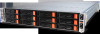
Hard disk drive sequence and LED indicators The hard drive sequence is as follows: Node B control panel Node D control panel Node A control panel Drive bays for node A Drive bays for node B Node C control panel Drive bays for node C Drive bays for node D Bay no. Node A HDD A0 to A2 Node B HDD B0 to B2 Node C HDD C0 to C2 Node D HDD D0 to D2 Description Three 3.5-inch hot-plug drive bays controlled by node A Three 3.5-inch hot-plug drive bays controlled by node B Three 3.5-inch hot-plug drive bays controlled by node C Three 3.5-inch hot-plug drive bays controlled by node D Drive activity LED indicators are mounted on the hot-plug HDD carrier. The table below lists the possible drive states. Description Blue Red HDD present no access Off Off HDD access Blink Off Rear panel LED indicators LED indicator System ID indicator LED color N/A Blue Blue LED state Off On Blinking Status Normal System identification IPMI-activated system ID Chapter 4 17