ASRock A320M User Manual
ASRock A320M Manual
 |
View all ASRock A320M manuals
Add to My Manuals
Save this manual to your list of manuals |
ASRock A320M manual content summary:
- ASRock A320M | User Manual - Page 1
- ASRock A320M | User Manual - Page 2
change without notice, and should not be constructed as a commitment by ASRock. ASRock assumes no responsibility for any errors or omissions that may appear in CALIFORNIA, USA ONLY The Lithium battery adopted on this motherboard contains Perchlorate, a toxic substance controlled in Perchlorate Best - ASRock A320M | User Manual - Page 3
replaced if the goods fail to be of acceptable quality and the failure does not amount to a major failure. If you require assistance please call ASRock Tel : +886-2-28965588 ext.123 (Standard International call charges apply) - ASRock A320M | User Manual - Page 4
1 Introduction 1 1.1 Package Contents 1 1.2 Specifications 2 1.3 Motherboard Layout 5 1.4 I/O Panel 9 Chapter 2 Installation 12 2.1 (NGFF) Module Installation Guide (M2_1) 33 Chapter 3 Software and Utilities Operation 36 3.1 Installing Drivers 36 3.2 ASRock Live Update & APP Shop - ASRock A320M | User Manual - Page 5
4.1 Introduction 45 4.1.1 UEFI Menu Bar 45 4.1.2 Navigation Keys 46 4.2 Main Screen 47 4.3 OC Tweaker Screen 48 4.4 Advanced Screen 49 4.4.1 CPU Configuration 50 4.4.2 North Bridge Configuration 51 4.4.3 South Bridge Configuration 52 4.4.4 Storage Configuration 53 4.4.5 Super IO - ASRock A320M | User Manual - Page 6
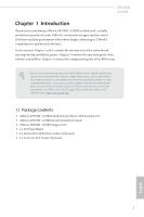
VGA cards and CPU support list on ASRock's website as well. ASRock website http://www.asrock.com. 1.1 Package Contents • ASRock AB350M / A320M Motherboard (Micro ATX Form Factor) • ASRock AB350M / A320M Quick Installation Guide • ASRock AB350M / A320M Support CD • 1 x I/O Panel Shield • 2 x Serial - ASRock A320M | User Manual - Page 7
9 Power Phase design • Supports 95W Air Cooling Chipset • AMD Promontory B350 (AB350M) • AMD Promontory A320 (A320M) Memory • Dual Channel Memory Support List on ASRock's website for more information. (http://www.asrock.com/) * Please refer to page 24 for DDR4 UDIMM maximum frequency support. - ASRock A320M | User Manual - Page 8
Supports ESD Protection) • 6 x USB 3.0 Ports (Supports ESD Protection) (AB350M) / 4 x USB 3.0 Ports (Supports ESD Protection) (A320M) • 1 x RJ-45 LAN Port with LED (ACT/LINK LED and SPEED LED) • HD (with A-Series APU)** ** Supports NVMe SSD as boot disks ** Supports ASRock U.2 Kit Connector • 1 x - ASRock A320M | User Manual - Page 9
multilingual GUI support • Supports "Plug and Play" • ACPI 5.1 compliance wake up events • Supports jumperfree • SMBIOS 2.3 support • DRAM ) * For detailed product information, please visit our website: http://www.asrock.com Please realize that there is a certain risk involved with overclocking, - ASRock A320M | User Manual - Page 10
1.3 Motherboard Layout AB350M: 1 AB350M A320M 23 PS2 Mouse PS2 Keyboard ATX12V1 CPU_FAN1 USB 2.0 T: USB1 B: USB2 DDR4_A1 (64 bit, 288-pin module) DDR4_B1 (64 bit, 288-pin module) USB 3.0 T: USB1 B: USB2 - ASRock A320M | User Manual - Page 11
No. Description 1 ATX 12V Power Connector (ATX12V1) 2 2 x 288-pin DDR4 DIMM Slots (DDR4_A1, DDR4_B1) 3 CPU Fan Connector (CPU_FAN1) 4 ATX Power Connector (ATXPWR1) 5 USB 3.0 Header (USB3_7_8) 6 USB 2.0 Header (USB_5_6) 7 USB 2.0 Header (USB_3_4) 8 SATA3 Connector (SATA3_3) 9 SATA3 Connector (SATA3_4 - ASRock A320M | User Manual - Page 12
(64 bit, 288-pin module) ATXPWR1 SOCKET AM4 RJ-45 LAN AMD_FAN_LED1 HD_AUDIO1 1 CMOS Battery 1 CHA_FAN1 USB3_7_8 CLRCMOS1 1 BIOS ROM A320M M2_1 RGB_LED1 1 PCIE1 M2_1_CT3 M2_1_CT2 M2_1_CT1 Ultra M.2 PCIe Gen3 x4 RoHS PCIE2 PCI Express 3.0 Super I/O TPMS1 1 COM1 1 CHA_FAN2 AMD - ASRock A320M | User Manual - Page 13
No. Description 1 ATX 12V Power Connector (ATX12V1) 2 2 x 288-pin DDR4 DIMM Slots (DDR4_A1, DDR4_B1) 3 CPU Fan Connector (CPU_FAN1) 4 ATX Power Connector (ATXPWR1) 5 USB 3.0 Header (USB3_7_8) 6 USB 2.0 Header (USB_5_6) 7 USB 2.0 Header (USB_3_4) 8 SATA3 Connector (SATA3_3) 9 SATA3 Connector (SATA3_4 - ASRock A320M | User Manual - Page 14
4 10 9 No. Description 1 PS/2 Mouse Port 2 LAN RJ-45 Port* 3 Line In (Light Blue)** 4 Front Speaker (Lime)** 5 Microphone (Pink)** A320M: 1 8 7 6 5 No. Description 6 USB 3.0 Ports (USB3_56) 7 USB 3.0 Ports (USB3_34) 8 USB 3.0 Ports (USB3_12) 9 USB 2.0 Ports (USB_12) 10 PS/2 Keyboard Port - ASRock A320M | User Manual - Page 15
* There are two LEDs on each LAN port. Please refer to the table below for the LAN port LED indications. ACT/LINK LED SPEED LED LAN Port Activity / Link LED Status Description Off Blinking On No Link Data Activity Link Speed LED Status Off Orange Green Description 10Mbps connection 100Mbps - ASRock A320M | User Manual - Page 16
AB350M A320M ** To configure 7.1 CH HD Audio, it is required to use an HD front panel audio module and enable the multichannel audio feature through the audio driver. Please set Speaker Configuration to "7.1 Speaker"in the Realtek HD Audio Manager. Function of the Audio Ports in 7.1-channel - ASRock A320M | User Manual - Page 17
it. Pre-installation Precautions Take note of the following precautions before you install motherboard components or change any motherboard settings. • Make sure to unplug the power cord before installing or removing the motherboard. Failure to do so may cause physical injuries to you and damages to - ASRock A320M | User Manual - Page 18
2.1 Installing the CPU Unplug all power cables before installing the CPU. 1 AB350M A320M 2 English 13 - ASRock A320M | User Manual - Page 19
3 14 English - ASRock A320M | User Manual - Page 20
AB350M A320M 2.2 Installing the CPU Fan and Heatsink After you install the CPU into this motherboard, it is necessary to install a larger heatsink and cooling fan to dissipate heat. You also need to spray thermal grease between the CPU and the - ASRock A320M | User Manual - Page 21
3 4 16 CPU_FAN1 English - ASRock A320M | User Manual - Page 22
Installing the AM4 Box Cooler SR2 1 AB350M A320M 2 English 17 - ASRock A320M | User Manual - Page 23
3 18 English - ASRock A320M | User Manual - Page 24
AB350M A320M 4 CPU_FAN1 5 RGB LED Cable 4-pin FAN cable CPU_FAN1 +12V AMD_FAN_LED1 *The diagram shown here are for reference only. Please refer to page 32 for the orientation of AMD Fan LED Header (AMD_FAN_LED1). 19 English - ASRock A320M | User Manual - Page 25
Installing the AM4 Box Cooler SR3 1 2 20 English - ASRock A320M | User Manual - Page 26
AB350M A320M 3 4 21 English - ASRock A320M | User Manual - Page 27
5 CPU_FAN1 22 English - ASRock A320M | User Manual - Page 28
AB350M A320M 6 CPU_FAN1 +12V AMD_FAN_LED1 or 7 CPU_FAN1 AMD_FAN_LED1 USB_5 Please note that only one cable should be used at a time in this step. If you select AMD_FAN_LED1, please install ASRock utility "ASRock RGB LED". If you select USB connector, please install AMD utility "SR3 Settings - ASRock A320M | User Manual - Page 29
installed. 3. It is not allowed to install a DDR, DDR2 or DDR3 memory module into a DDR4 slot; otherwise, this motherboard and DIMM may be damaged. DDR4 UDIMM Maximum Frequency Support A-Series APUs: UDIMM Memory Slot A1 B1 - SR SR - - DR DR - SR SR DR DR Frequency (Mhz) 2400 - ASRock A320M | User Manual - Page 30
AB350M A320M The DIMM only fits in one correct orientation. It will cause permanent damage to the motherboard and the DIMM if you force the DIMM into the slot at incorrect orientation. 1 2 3 25 English - ASRock A320M | User Manual - Page 31
2.4 Expansion Slots (PCI Express Slots) There are 2 PCI Express slots on the motherboard. Before installing an expansion card, please make sure that the power supply is switched off or the power cord is unplugged. Please read the documentation - ASRock A320M | User Manual - Page 32
AB350M A320M 2.5 Jumpers Setup The illustration shows how jumpers are setup. When the jumper cap is placed on the pins, the jumper is "Short". If no jumper - ASRock A320M | User Manual - Page 33
NOT place jumper caps over these headers and connectors. Placing jumper caps over the headers and connectors will cause permanent damage to the motherboard. System Panel Header (9-pin PANEL1) (see p.5 or 7, No. 12) PLED+ PLEDPWRBTN# GND 1 GND RESET# GND HDLEDHDLED+ Connect the power switch, reset - ASRock A320M | User Manual - Page 34
AB350M A320M SPEAKER DUMMY DUMMY +5V 1 SIGNAL GND DUMMY Please connect the chassis intrusion and the chassis speaker to this header. These four SATA3 connectors support SATA data cables for internal storage devices with up to 6.0 Gb/s data transfer rate. There are two headers on this motherboard - ASRock A320M | User Manual - Page 35
support HDA to function correctly. Please follow the instructions in our manual and chassis manual to install your system. 2. If you use an AC the HD audio panel only. You don't need to connect them for the AC'97 No. 4) 12 24 1 13 This motherboard provides a 24-pin ATX power connector. To - ASRock A320M | User Manual - Page 36
D LAD1 LAD2 SMB_DATA_MAIN SMB_CLK_MAIN GN D +3VS B LAD0 +3V LAD3 PCIRST # FRAM E PCICLK AB350M A320M 8 5 This motherboard provides a 8-pin ATX 12V 4 1 power connector. To use a 4-pin ATX power supply, please refer to page 43 for for further instructions on these two headers. English 31 - ASRock A320M | User Manual - Page 37
AMD FAN LED Header (4-pin AMD_FAN_ LED1) (see p.5 or 7, No. 21) AMD FAN LED Header is used to connect RGB LED extension cable that comes with AMD heatsink. The cable connection allows users to choose from various LED lighting effects. Caution: Never install the FAN LED cable in the wrong - ASRock A320M | User Manual - Page 38
AB350M A320M 2.7 M.2_SSD (NGFF) Module Installation Guide (M2_1) The M.2, also known as the Next Generation Form Factor (NGFF), is a small size and versatile card edge connector that aims to replace mPCIe and mSATA. The Ultra M.2 Socket (M2_1) supports type 2242/2260/2280 M.2 PCI Express module up - ASRock A320M | User Manual - Page 39
hand. Step 4 Peel off the yellow protective film on the nut to be used. Hand tighten the standoff into the desired nut location on the motherboard. Step 5 Align and gently insert the M.2 (NGFF) SSD module into the M.2 slot. Please be aware that the M.2 (NGFF) SSD module only fits in one orientation - ASRock A320M | User Manual - Page 40
A320M Step 6 Tighten the screw with a screwdriver to secure the module into place. Please do not overtighten the screw as this might damage the module. M.2_SSD (NGFF) Module Support of M.2_SSD (NFGG) module support list, please visit our website for details: http://www.asrock.com English 35 - ASRock A320M | User Manual - Page 41
drivers. Therefore, the drivers you install can work properly. Utilities Menu The Utilities Menu shows the application software that the motherboard supports. Click on a specific item then follow the installation wizard to install it. To improve Windows 7 compatibility, please download and install - ASRock A320M | User Manual - Page 42
store for purchasing and downloading software applications for your ASRock computer. You can quickly and easily install various apps and support utilities. With ASRock Live Update & APP Shop, you can optimize your system and keep your motherboard up to date simply with a few clicks. Double-click - ASRock A320M | User Manual - Page 43
3.2.2 Apps When the "Apps" tab is selected, you will see all the available apps on screen for you to download. Installing an App Step 1 Find the app you want to install. The most recommended app appears on the left side of the screen. The other various apps are shown on the right. Please scroll up - ASRock A320M | User Manual - Page 44
Step 3 If you want to install the app, click on the red icon AB350M A320M to start downloading. Step 4 When installation completes, you can find the green "Installed" icon appears on the upper right corner. English To uninstall it, simply - ASRock A320M | User Manual - Page 45
Upgrading an App You can only upgrade the apps you have already installed. When there is an available new version for your app, you will find the mark of "New Version" appears below the installed app icon. Step 1 Click on the app icon to see more details. Step 2 Click on the yellow icon to start - ASRock A320M | User Manual - Page 46
AB350M A320M 3.2.3 BIOS & Drivers Installing BIOS or Drivers When the "BIOS & Drivers" tab is selected, you will see a list of recommended or critical updates for the BIOS - ASRock A320M | User Manual - Page 47
3.2.4 Setting In the "Setting" page, you can change the language, select the server location, and determine if you want to automatically run the ASRock Live Update & APP Shop on Windows startup. 42 English - ASRock A320M | User Manual - Page 48
AB350M A320M 3.3 ASRock RGB LED ASRock RGB LED is a lighting control utility specifically Failure to do so may cause damages to motherboard components. 1. Please note that the RGB LED strips do not come with the package. 2. The RGB LED header supports standard 5050 RGB LED strip (12V/G/R/B), with - ASRock A320M | User Manual - Page 49
LED utility. Download this utility from the ASRock Live Update & APP Shop and start coloring your PC style your way! Drag the tab to customize your preference. Toggle on/off the RGB LED switch Sync RGB LED effects for all LED regions of the motherboard Select a RGB LED light effect from the - ASRock A320M | User Manual - Page 50
AB350M A320M Chapter 4 UEFI SETUP UTILITY 4.1 Introduction This section explains how to use the UEFI SETUP UTILITY to configure your system. You may run the UEFI SETUP - ASRock A320M | User Manual - Page 51
4.1.2 Navigation Keys Use < > key or < > key to choose among the selections on the menu bar, and use < > key or < > key to move the cursor up or down to select items, then press to get into the sub screen. You can also use the mouse to click your required item. Please check the following - ASRock A320M | User Manual - Page 52
4.2 Main Screen When you enter the UEFI SETUP UTILITY, the Main screen will appear and display the system overview. AB350M A320M AB350M: A320M: 47 English - ASRock A320M | User Manual - Page 53
4.3 OC Tweaker Screen In the OC Tweaker screen, you can set up overclocking features. Because the UEFI software is constantly being updated, the following UEFI setup screens and descriptions are for reference purpose only, and they may not exactly match what you see on your screen. Voltage - ASRock A320M | User Manual - Page 54
AB350M A320M 4.4 Advanced Screen In this section, you may set the configurations for ] is selected, the resolution will be set to 1920 x 1080 if the monitor supports Full HD resolution. If the monitor does not support Full HD resolution, then the resolution will be set to 1024 x 768. When [Disable] - ASRock A320M | User Manual - Page 55
4.4.1 CPU Configuration Cool 'n' Quiet Use this item to enable or disable AMD's Cool 'n' QuietTM technology. The default value is [Enabled]. Configuration options: [Enabled] and [Disabled]. If you install Windows® OS and want to enable this function, please set this item to [Enabled]. Please note - ASRock A320M | User Manual - Page 56
4.4.2 North Bridge Configuration AB350M A320M IOMMU Use this to enable or disable IOMMU. The default value of this feature is [Disabled]. Share Memory Configure the size of memory that is allocated to the integrated graphics processor when the system boots up. English 51 - ASRock A320M | User Manual - Page 57
and automatically disable it when a sound card is installed. Front Panel Enable/disable front panel HD audio. Deep Sleep Configure deep sleep mode for power saving when the computer is shut down. Restore on AC/Power Loss Select the power state after a power failure. If [Power Off] is selected, the - ASRock A320M | User Manual - Page 58
4.4.4 Storage Configuration AB350M A320M SATA Controller(s) Enable/disable the SATA controllers. SATA Mode AHCI: Supports new features that improve performance. RAID: Combine multiple disk drives into a logical unit. 53 English - ASRock A320M | User Manual - Page 59
4.4.5 Super IO Configuration Serial Port Enable or disable the Serial port. Serial Port Address Select the address of the Serial port. 54 English - ASRock A320M | User Manual - Page 60
4.4.6 ACPI Configuration AB350M A320M Suspend to RAM It is recommended to select auto for ACPI S3 power saving. ACPI HPET Table Enable the High Precision Event Timer for better - ASRock A320M | User Manual - Page 61
4.4.7 Trusted Computing Security Device Support Enable to activate Trusted Platform Module (TPM) security for your hard disk drives. 56 English - ASRock A320M | User Manual - Page 62
4.5 Tools AB350M A320M RGB LED ASRock RGB LED allows you to adjust the RGB LED color to your liking. Easy RAID Installer Easy RAID Installer helps you to copy the RAID driver from the support CD to your USB storage device. After copying the drivers please change the SATA mode to RAID, then you - ASRock A320M | User Manual - Page 63
Flash Save UEFI files in your USB storage device and run Instant Flash to update your UEFI. Internet Flash - DHCP (Auto IP), Auto ASRock Internet Flash downloads and updates the latest UEFI firmware version from our servers for you. Please setup network configuration before using Internet Flash - ASRock A320M | User Manual - Page 64
AB350M A320M 4.6 Hardware Health Event Monitoring Screen This section allows you to monitor the status of the hardware on your system, including the parameters of the CPU temperature, motherboard temperature, fan speed and voltage. CPU Fan 1 Setting Select a fan mode for CPU Fan 1, or choose - ASRock A320M | User Manual - Page 65
are unable to change the settings in the UEFI Setup Utility. Leave it blank and press enter to remove the password. Secure Boot Enable to support Secure Boot. 60 English - ASRock A320M | User Manual - Page 66
AB350M A320M 4.8 Boot Screen This section displays the available devices on your system for you to configure the boot settings and the boot priority. Fast Boot Fast - ASRock A320M | User Manual - Page 67
messages or configure the AddOn ROM if you've enabled Full Screen Logo. Disable for faster boot speed. CSM (Compatibility Support Module) CSM Enable to launch the Compatibility Support Module. Please do not disable unless you're running a WHCK test. Launch PXE OpROM Policy Select UEFI only to run - ASRock A320M | User Manual - Page 68
4.9 Exit Screen AB350M A320M Save Changes and Exit When you select this option the following message, "Save configuration changes and exit setup?" will pop out. Select [OK] to save - ASRock A320M | User Manual - Page 69
or want to know more about ASRock, you're welcome to visit ASRock's website at http://www.asrock.com; or you may contact your dealer for further information. For technical questions, please submit a support request form at http://www.asrock.com/support/tsd.asp ASRock Incorporation 2F., No.37, Sec
-
 1
1 -
 2
2 -
 3
3 -
 4
4 -
 5
5 -
 6
6 -
 7
7 -
8
-
9
-
10
-
11
-
12
-
13
-
14
-
15
-
16
-
17
-
18
-
19
-
20
-
21
-
22
-
23
-
24
-
25
-
26
-
27
-
28
-
29
-
30
-
31
-
32
-
33
-
34
-
35
-
36
-
37
-
38
-
39
-
40
-
41
-
42
-
43
-
44
-
45
-
46
-
47
-
48
-
49
-
50
-
51
-
52
-
53
-
54
-
55
-
56
-
57
-
58
-
59
-
60
-
61
-
62
-
63
-
64
-
65
-
66
-
67
-
68
-
69
 |
 |
